![]()
Ultra Messaging (Version 6.17.1)
[ Multi-page HTML ] | [ PDF ]
Introduction <-
This document explains design concepts and product implementation for the Ultra Messaging Dynamic Routing Option (DRO).
For policies and procedures related to Ultra Messaging Technical Support, see UM Support.
(C) Copyright 2004,2025 Informatica Inc. All Rights Reserved.
This software and documentation are provided only under a separate license agreement containing restrictions on use and disclosure. No part of this document may be reproduced or transmitted in any form, by any means (electronic, photocopying, recording or otherwise) without prior consent of Informatica LLC.
A current list of Informatica trademarks is available on the web at https://www.informatica.com/trademarks.html.
Portions of this software and/or documentation are subject to copyright held by third parties. Required third party notices are included with the product.
This software is protected by patents as detailed at https://www.informatica.com/legal/patents.html.
The information in this documentation is subject to change without notice. If you find any problems in this documentation, please report them to us in writing at Informatica LLC 2100 Seaport Blvd. Redwood City, CA 94063.
Informatica products are warranted according to the terms and conditions of the agreements under which they are provided.
INFORMATICA LLC PROVIDES THE INFORMATION IN THIS DOCUMENT "AS IS" WITHOUT WARRANTY OF ANY KIND, EXPRESS OR IMPLIED, INCLUDING WITHOUT ANY WARRANTIES OF MERCHANTABILITY, FITNESS FOR A PARTICULAR PURPOSE AND ANY WARRANTY OR CONDITION OF NON-INFRINGEMENT.
The Ultra Messaging Dynamic Routing Option (DRO) consists of a daemon named "tnwgd" that bridges disjoint Topic Resolution Domains (TRDs) by effectively forwarding control and user traffic between them. Thus, the DRO facilitates WAN routing where multicast routing capability is absent, possibly due to technical obstacles or enterprise policies.
FYI: for historical reasons, the DRO has gone by several names:
- Gateway
- tnwg = "Twenty Nine West Gateway"
- UM Router
- Dynamic Router
- DRO = Dynamic Routing Option
In the UM documentation, the term "DRO" is generally used for brevity, but sometimes various abbreviations that include "tnwg" are used.
DRO Features <-
The DRO includes the following features:
- Full bidirectional forwarding
- Multi-hop forwarding
- Mesh, loop, or alternate path DRO configurations
- Automatic rerouting around faults
- Support for wildcard receivers
- Support of Request/Response messages
- Traffic filtering on multiple criteria
- DRO resilience
- UMP persistence support
- UM transport monitoring statistics
- Web Monitoring
- MIM and UIM forwarding
The following features are not fully supported in this release of the DRO:
- Queuing, both ULB and Brokered (including brokered JMS)
- Multitransport Threads (MTT)
If you desire any of these features or any configuration or topology not presented in this document, please contact UM Support.
- Note
- The DRO is not directly supported on the OpenVMS platform. UM applications running on the OpenVMS platform, however, can use a DRO running on a different platform, such as Microsoft Windows or Linux.
DRO Architecture <-
DRO Portals <-
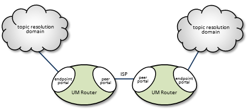
The DRO uses interfaces, called portals, through which to pass data. A DRO consists of two or more bidirectional portals that may be one of two types:
- An endpoint portal, which communicates directly to a UM topic resolution domain (TRD; see Topic Resolution Domains).
- A peer portal, which communicates via TCP with another peer portal (of another DRO), allowing tunneling between DROs. Two peer portals connected to each other are referred to as companion peers, and by default, utilize TCP connections for data and control traffic. Compression and encryption can be applied to TCP-only peer links. Optionally, latency can be reduced by adding UDP to the peer link; see UDP Peer Link.
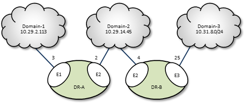
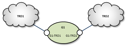
The figure below shows a simple DRO use case, where two DROs bridge an ISP to connect two TRDs using a TCP link.
You configure portals in the DRO's XML configuration file, specifying the portal's name, cost, UM Configuration, Access Control Lists and other attributes. See DRO Configuration Reference.
UDP Peer Link <-
By default, a DRO peer link uses a single TCP connection to communicate between two DROs. But TCP can introduce latency outliers and limit throughput, especially when used over a high-bandwidth, high-latency WAN link that experiences occasional packet loss. Latency and throughput can be improved by enabling the UDP peer link option.
When UDP is enabled for a peer link, the TCP peer link is still used for DRO command and control messages. Everything else, including user data, is exchanged using UDP.
To enable UDP on a peer link, use the Router Element "<udp>". At a minimum, you must configure the port number.
When configured, both the TCP and the UDP links must be operational. If either link fails to pass data, the DRO will disconnect and reconnect until both links are successful.
The UDP peer link uses the same reliable unicast protocol as the Transport LBT-RU protocol, and shares many of the same configuration options as the transport. However, unlike LBT-RU, the UDP peer link does not need to have a datagram maximum size configured. It is hard-coded to a large value (above 65,000 bytes), chosen to be sufficient to handle all valid UM fragment sizes.
Starting with UM version 6.17, the UDP Peer link supports compression and encryption. See Router Element "<compression>" and Router Element "<tls>".
Topic Resolution Domains <-
Since topic resolution uses UDP, sources and receivers must have UDP connectivity to each other. When they do, we consider them to be in the same topic resolution domain (TRD). More specifically, UM contexts must satisfy the following two requirements to belong to the same topic resolution domain.
- The contexts must use the same topic resolution UM configuration (i.e., resolver_* options are the same).
- Contexts can communicate using the protocols required for both message transport and topic resolution traffic.
For example, two contexts on separate machines in the same LAN are not in the same topic resolution domain if they use different resolver addresses. See Multicast Resolver Network Options. A topic resolution domain can span a WAN if the UM contexts on each side of a firewall use the same UM configuration and the firewall allows UDP traffic (multicast or unicast) to pass.
Each endpoint portal must identify its associated topic resolution domain with a domain-id the DRO's XML configuration file, as in the example below. All portals in the same TRD must have the same domain-id, and different TRDs networked together via DROs must have domain-ids unique to each other.
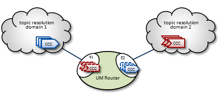
Proxy Sources and Proxy Receivers <-
To resolve a topic across a DRO (described in Basic DRO Operation), the DRO creates, within portals, proxy sources and proxy receivers (shown in the figure below by their dashed lines). These proxies behave like their UM counterparts; they resolve topics on the TRDs like normal sources and receivers, and the DRO internally passes data from one portal to the other. However unlike regular sources, proxy sources do not have retransmission retention buffers normally used for Late Join or OTR.
Portals exist while the DRO is running, however, the DRO creates proxy sources and receivers during topic resolution and deletes them when the topic is retired.
- Note
- The proxy sources created by the DRO are unrelated to proxy sources created by the UMP persistent store.
DRO and Transport Sessions <-
When the DRO creates proxy receivers to get messages to forward, be aware that the transport sessions carrying those messages are not extended to the destination TRD. Instead, the proxy receiver simply takes the messages from the originating transport sessions and transfers them to the destination DRO's proxy sources. Those proxy sources create new transport sessions for those outgoing messages.
The proxy sources' outgoing transport sessions are unrelated to the originating sources' transport sessions. They can even use different transport types, performing a protocol conversion. In fact, a single transport session can contain multiple sources from different originating publishing applications for the same topic. Alternatively, multiple sources from the same originating publishing application which are mapped to the same originating transport session can be split into multiple transport sessions by the proxy sources in a remote TRD.
One consequence of the independence of incoming and outgoing transport sessions is that TCP flow control does not transit the DRO. A slow receiver in a remote TRD cannot "push back" on a fast source. In cases where a TCP transport session is slowed down due to one or more slow receivers, an intermediate DRO will eventually have to drop messages.
- Warning
- A single source's "source string" will be different in different TRDs connected by DROs. See Source Strings in a Routed Network for details.
Routing <-
In multiple-DRO environments where more than one DRO can provide possible messaging pathways, the DROs are able to cooperatively determine and establish optimal routes. Also, the DRO network is able to detect link or other DRO outages and automatically reroute traffic as needed. See Routing Topologies for more information.
DRO Concepts <-
Basic DRO Operation <-
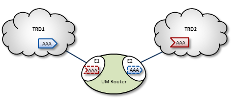
The DRO's routing algorithm is said to be "interest-based". That is, subscribers express interest in topic names and/or wildcard topic patterns. The DRO network maintains lists of topics and patterns for each TRD, and routes messages accordingly.
The diagram below shows a DRO bridging topic resolution domains TRD1 and TRD2, for topic AAA, in a direct link configuration. Endpoint E1 contains a proxy receiver for topic AAA and endpoint E2 has a proxy source for topic AAA.
To establish topic resolution in an already-running DRO, the following sequence typically occurs in an example like the above figure.
- A receiver in TRD2 issues a TQR (Topic Query Record) for topic AAA.
- Portal E2 receives the TQR and passes information about topic AAA to all other portals in the DRO. (In this case, E1 is the only other portal.)
- E1 immediately responds with three actions: a) create a proxy receiver for topic AAA, b) the new proxy receiver sends a TQR for AAA into TRD1, and c) E1 issues a Topic Interest message into TRD1 for the benefit of any other DROs that may be connected to that domain.
- A source for topic AAA in TRD1 sees the TQR and issues a TIR (Topic Information Record).
- E2 creates proxy source AAA, which then issues a TIR to TRD2. The receiver in TRD2 joins the transport, thus completing topic resolution.
- E1's AAA proxy receiver sees the TIR and requests that E2 (and any other interested portals in the DRO, if there were any) create a proxy source for AAA.
Interest and Topic Resolution <-
As mentioned in Basic DRO Operation, the DRO's routing algorithm is "interest-based". The DRO uses UM's Topic Resolution (TR) protocol to discover and maintain the interest tables.
For TCP-based TR, the SRS informs DROs of receiver topics and wildcard receiver patterns.
For UDP-based TR, the application's TR queries are used to inform DROs of its receiver topics and wildcard receiver patterns.
- Attention
- If using UDP-based TR, do not disable querying, as that would prevent the DRO from discovering topic and pattern interest.
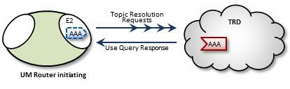
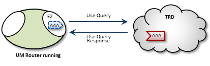
Interest and Use Queries <-
When a DRO starts, its endpoint portals issue a brief series of Topic Resolution Request messages to their respective topic resolution domains. This provokes quiescent receivers (and wildcard receivers) into sending Use Query Responses, indicating interest in various topics. Each portal then records this interest.
After a DRO has been running, endpoint portals issue periodic Topic Use Queries and Pattern Use Queries (collectively referred to as simply Use Queries). Use Query Responses from UM contexts confirm that the receivers for these topics indeed still exist, thus maintaining these topics on the interest list. Autonomous TQRs also refresh interest and have the effect of suppressing the generation of Use Queries.
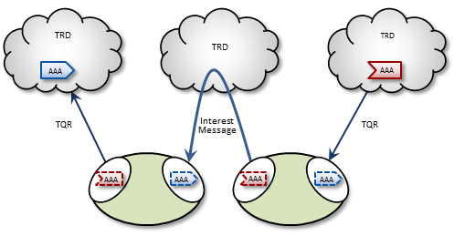
In the case of multi-hop DRO configurations, DROs cannot detect interest for remote contexts via Use Queries or TQRs. They do this instead via Interest Messages. An endpoint portal generates periodic interest messages, which are picked up by adjacent DROs (i.e., the next hop over), at which time interest is refreshed.
You can adjust intervals, limits, and durations for these topic resolution and interest mechanisms via DRO configuration options (see DRO Configuration Reference).
DRO Keepalive <-
To maintain a reliable connection, peer portals exchange DRO Keepalive signals. Keepalive intervals and connection timeouts are configurable on a per-portal basis. You can also set the DRO to send keepalives only when traffic is idle, which is the default condition. When both traffic and keepalives go silent at a portal ingress, the portal considers the connection lost and disconnects the TCP link. After the disconnect, the portal tries to reconnect. See <gateway-keepalive>.
Final Advertisements <-
DRO proxy sources on endpoint portals, when deleted, send out a series of final advertisements. A final advertisement tells any receivers, including proxy receivers on other DROs, that the particular source has gone away. This triggers EOS and clean-up activities on the receiver relative to that specific source, which causes the receiver to begin querying according to its topic resolution configuration for the sustaining phase of querying.
In short, final advertisements announce earlier detection of a source that has gone away, instead of transport timeout. This causes a faster transition to an alternative proxy source on a different DRO if there is a change in the routing path.
More About Proxy Sources and Receivers <-
The domain-id is used by Interest Messages and other internal and DRO-to-DRO traffic to ensure forwarding of all messages (payload and topic resolution) to the correct recipients. This also has the effect of not creating proxy sources/receivers where they are not needed. Thus, DROs create proxy sources and receivers based solely on receiver interest.
If more than one source sends on a given topic, the receiving portal's single proxy receiver for that topic receives all messages sent on that topic. The sending portal, however creates a proxy source for every source sending on the topic. The DRO maintains a table of proxy sources, each keyed by an Originating Transport ID (OTID), enabling the proxy receiver to forward each message to the correct proxy source. An OTID uniquely identifies a source's transport session, and is included in topic advertisements.
Protocol Conversion <-
When an application creates a source, it is configured to use one of the UM transport types. When a DRO is deployed, the proxy sources are also configured to use one of the UM transport types. Although users often use the same transport type for sources and proxy sources, this is not necessary. When different transport types are configured for source and proxy source, the DRO is performing a protocol conversion.
When this is done, it is very important to configure the transports to use the same maximum datagram size. If you don't, the DRO can drop messages which cannot be recovered through normal means. For example, a source in Topic Resolution Domain 1 might be configured for TCP, which has a default maximum datagram size of 65536. If a DRO's remote portal is configured to create LBT-RU proxy sources, that has a default maximum datagram size of 8192. If the source sends a user message of 10K, the TCP source will send it as a single fragment. The DRO will receive it and will attempt to forward it on an LBT-RU proxy source, but the 10K fragment is too large for LBT-RU's maximum datagram size, so the message will be dropped.
See Message Fragmentation and Reassembly.
The solution is to override the default maximum datagram sizes to be the same. Informatica generally does not recommend configuring UDP-based transports for datagram sizes above 8K, so it is advisable to set the maximum datagram sizes of all transport types to 8192, like this:
context transport_tcp_datagram_max_size 8192
context transport_lbtrm_datagram_max_size 8192
context transport_lbtru_datagram_max_size 8192
context transport_lbtipc_datagram_max_size 8192
source transport_lbtsmx_datagram_max_size 8192
Note that users of a kernel bypass network driver (e.g. Solarflare's Onload) frequently want to avoid all IP fragmentation, and therefore want to set their datagram max sizes to an MTU. See Datagram Max Size and Network MTU and Dynamic Fragmentation Reduction.
Configuration options: transport_tcp_datagram_max_size (context), transport_lbtrm_datagram_max_size (context), transport_lbtru_datagram_max_size (context), transport_lbtipc_datagram_max_size (context), and transport_lbtsmx_datagram_max_size (source).
Final note: the resolver_datagram_max_size (context) option also needs to be made the same in all instances of UM, including DROs.
Multi-Hop Forwarding <-
UM can resolve topics across a span of multiple DROs. Consider a simple example DRO deployment, as shown in the following figure.
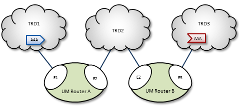
In this diagram, DRO A has two endpoint portals connected to topic resolution domains TRD1 and TRD2. DRO B also has two endpoint portals, which bridge TRD2 and TRD3. Endpoint portal names reflect the topic resolution domain to which they connect. For example, DRO A endpoint E2 interfaces TRD2.
TRD1 has a source for topic AAA, and TRD3, an AAA receiver. The following sequence of events enables the forwarding of topic messages from source AAA to receiver AAA.
- Receiver AAA queries (issues a TQR).
- DRO B, endpoint E3 (B-E3) receives the TQR and passes information about topic AAA to all other portals in the DRO. In this case, B-E2 is the only other portal.
- In response, B-E2 creates a proxy receiver for AAA and sends a Topic Interest message for AAA into TRD2. The proxy receiver also issues a TQR, which in this case is ignored.
- DRO A, endpoint E2 (A-E2) receives this Topic Interest message and passes information about topic AAA to all other portals in the DRO. In this case, A-E1 is the only other portal.
- In response, A-E1 creates a proxy receiver for AAA and sends a Topic Interest message and TQR for AAA into TRD1.
- Source AAA responds to the TQR by sending a TIR for topic AAA. In this case, the Topic Interest message is ignored.
- The AAA proxy receiver created by A-E1 receives this TIR and requests that all DRO A portals with an interest in topic AAA create a proxy source for AAA.
- In response, A-E2 creates a proxy source, which sends a TIR for topic AAA via TRD2.
- The AAA proxy receiver at B-E2 receives this TIR and requests that all DRO B portals with an interest in topic AAA create a proxy source for AAA.
- In response, B-E3 creates a proxy source, which sends a TIR for topic AAA via TRD3. The receiver in TRD3 joins the transport.
- Topic AAA has now been resolved across both DROs, which forward all topic messages sent by source AAA to receiver AAA.
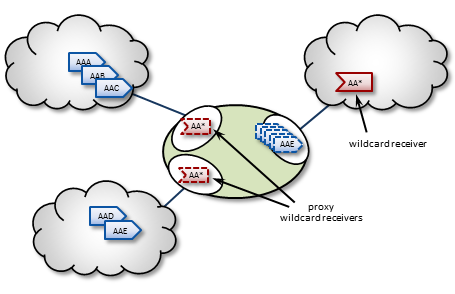
Routing Wildcard Receivers <-
The DRO supports topic resolution for wildcard receivers in a manner very similar to non-wildcard receivers. Wildcard receivers in a TRD issuing a WC-TQR cause corresponding proxy wildcard receivers to be created in portals, as shown in the following figure. The DRO creates a single proxy source for pattern match.
Forwarding Costs <-
Forwarding a message through a DRO incurs a cost in terms of latency, network bandwidth, and CPU utilization on the DRO machine (which may in turn affect the latency of other forwarded messages). Transiting multiple DROs adds even more cumulative latency to a message. Other DRO-related factors such as portal buffering, network bandwidth, switches, etc., can also add latency.
Factors other than latency contribute to the cost of forwarding a message. Consider a message that can be sent from one domain to its destination domain over one of two paths. A three-hop path over 1Gbps links may be faster than a single-hop path over a 100Mbps link. Further, it may be the case that the 100Mbps link is more expensive or less reliable.
You assign forwarding cost values on a per-portal basis. When summed over a path, these values determine the cost of that entire path. A network of DROs uses forwarding cost as the criterion for determining the best path over which to resolve a topic.
DRO Routing <-
DROs have an awareness of other DROs in their network and how they are linked. Thus, they each maintain a topology map, which is periodically confirmed and updated. This map also includes forwarding cost information.
Using this information, the DROs can cooperate during topic resolution to determine the best (lowest cost) path over which to resolve a topic or to route control information. They do this by totaling the costs of all portals along each candidate route, then comparing the totals.
For example, the following figure shows two possible paths from TRD1 to TRD2: A-C (total route cost of 11) and B-D (total route cost of 7). In this case, the DROs select path B-D.
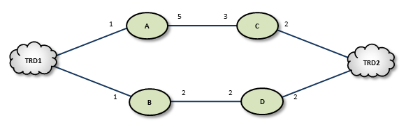
If a DRO or link along path B-D should fail, the DROs detect this and reroute over path A-C. Similarly, if an administrator revises cost values along path B-D to exceed a total of 12, the DROs reroute to A-C.
If the DROs find more than one path with the same lowest total cost value, i.e., a "tie", they select the path based on a node-ID selection algorithm. Since administrators do not have access to node IDs, this will appear to be a pseudo-random selection.
In normal usage, you cannot configure parallel paths (such as for load balancing or Hot failover), as the DROs always select the lowest-cost path and only the lowest-cost path for all data between two points.
An exception to this rule is DRO Hotlinks (see next section).
DRO Hotlinks <-
The DRO "hotlink" feature is intended for large UM deployments where multiple datacenters are interconnected by two independent global networks. The function of the DRO hotlinks feature is to implement a form of Hot Failover (HF) whereby two copies of each message are sent in parallel over the two global networks from a publishing datacenter to subscribing datacenters. The subscribing process will normally receive both copies of each message, but UM will deliver the first one it receives and discard the second.
The purpose for this feature is to provide high availability in the face of failure of a global network. It is unlikely that both global networks will fail at the same time, so if one does fail, the messages flowing over the other network will continue to provide connectivity without the need to perform an explicit "fail over" operation (which can introduce temporary packet loss and latency).
Hotlinks: Logical Interpretation <-
Hotlinks operate on a Topic Resolution Domain ("TRD") basis. Here is a typical hotlink topology:
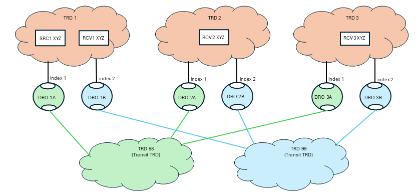
The primary job of the DRO is to connect TRDs together. In the above diagram, messages for topic "XYZ" published by SRC1 are received by RCV1, RCV2, and RCV3.
Let's consider RCV3. There are two possible paths to get from SRC to RCV3: transiting through TRD 98 and transiting through TRD 99. If this were a normal (not hotlinked) DRO deployment, UM would determine which path has the lowest cost and would route all messages through that path, not using the other path at all. With the hotlinks feature enabled, both DRO 1A and DRO 1B will create proxy receivers for topic XYZ and both will forward every message across the corresponding transit TRD to the destination. Once in the destination TRD 3, both copies of each message are received by the subscribing application RCV3, and UM will deliver the first one that arrives and discard the second.
To enable the hotlinks feature, you must:
- Define a hotlink index and a route group on each hotlinked DRO's portal connected to the datacenter (not the redundant WAN links). (More information on these settings below.)
- Configure the source and receiver for "use_hotlink".
A DRO is configured to operate in a hotlinked fashion by setting the hotlink index. When assigning hotlink index values, each DRO operating in hotlinked mode must have different index value for endpoint portals within a given TRD. In the above diagram, DROs 1A and 1B must have different index values. But they do not have to be unique across the entire network. So the index values in one TRD can overlap with indices used in other TRDs. Note that there is no need to use the same index value for the corresponding DROs in each hotlinked TRD (i.e. DROs 1A, 2A, and 3A do not need to use the same indices).
The route group values are intended to show which DRO portals should operate in hotlink mode with respect to each other. DROs 1A and 1B use the same route group, and therefore will operate in hot-hot mode. This allows the mixing of multiple hotlink groups and non-hotlinked DROs in the same TRD. See Mixing Regular and Hotlinked DROs. The route group is only meaningful for DRO portals configured with a hotlink index.
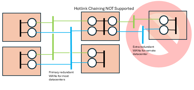
Hotlinks: Physical Interpretation <-
Normally there is no expectation of mapping between TRDs and the physical entities (networks, datacenters, hosts). The distribution of programs to TRDs is logical, not physical. However, the hotlinks feature deviates from that pattern with the expectation that TRDs map onto specific physical entities. Here is the previous logical TRD network shown in its physical embodiment:
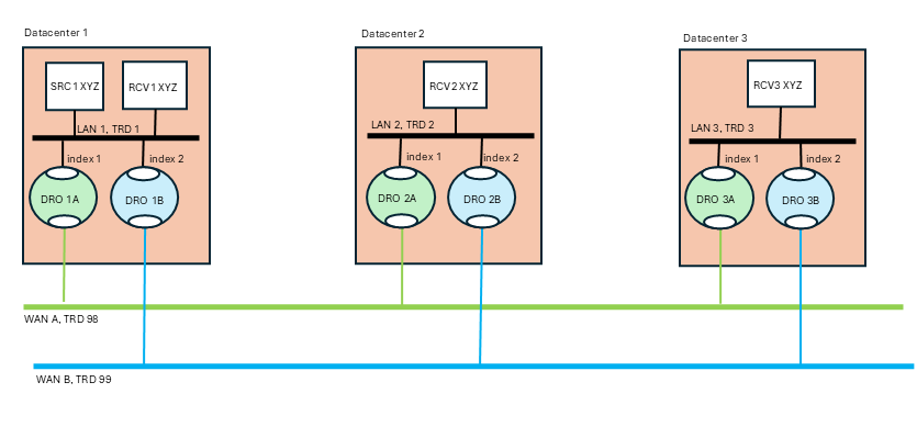
The above diagram is a "dual hub with spokes" topology where the two WAN-based TRDs are the hubs and the data centers are the spokes. It is assumed that each data center's LAN uses LBT-RM (multicast) transports, although this is not strictly necessary.
The publisher for topic "XYZ" (SRC1) is in datacenter 1. It sends a single message via multicast onto LAN 1. The subscriber "RCV1" will receive a copy of the message, as will the two DROs labeled "1A" and "1B". Those DROs will forward the message onto "WAN A" and "WAN B" respectively. Now you have two copies of the message. Let's follow the message into datacenter 2 via DROs "2A" and "2B". Each DRO receives its respective copy of each message and forwards it onto LAN 2. Note there are still two copies of the message on LAN 2. Finally receiver "RCV2" gets both copies of the message, and UM's "hot failover" logic delivers the first one to the application and discards the second one.
Note that the WAN TRDs can also use multicast, or can be configured for unicast-only operation. In fact, even the LANs can be used in unicast mode, although that will force the publisher "SRC1" to send the message three times, to RCV1, DRO 1A, and DRO 1B.
The benefit of the hotlinks feature is that if WAN A fails, the receivers for XYZ will not detect any disruption or latency outliers - WAN B will continue carrying the messages. There is no "fail over" sequence. A downside of this design is that the receivers will experience twice the packet load. However, also note that the second copy of each message is discarded inside UM, so no application overhead is consumed.
The hotlinks feature is intended to be used in deployments similar to the above diagram, with DROs interconnecting multiple datacenters. It is not designed to handle redundancy within a datacenter.
Example DRO Configuration <-
Here is the configuration for "DRO 1A" referenced in the previous sections:
<?xml version="1.0" encoding="UTF-8" ?>
<tnw-gateway version="1.0">
  <daemon>
    <name>dro_1A</name>
    <log type="console"/>
    <pidfile>dro_1A.pid</pidfile>
    <xml-config>um.xml</xml-config>
  </daemon>
  <portals>
    <endpoint>
      <name>TRD1</name>
      <domain-id>1</domain-id>
      <cost>1</cost>
      <hotlink-index>1</hotlink-index>
      <route-group>1</route-group>
      <lbm-attributes>
        <option name="context_name" scope="context" value="dro_1A-1"/>
      </lbm-attributes>
    </endpoint>
    <endpoint>
      <name>TRD98</name>
      <domain-id>98</domain-id>
      <cost>1</cost>
      <lbm-attributes>
        <option name="context_name" scope="context" value="dro_1A-98"/>
      </lbm-attributes>
    </endpoint>
  </portals>
</tnw-gateway>
Some notes:
- No peer link portals are used. Only endpoint portals.
- The portals' associated contexts are named so that the "um.xml" file can configure the contexts independently by context name.
- Portal TRD1 has a hotlink index defined. Portal TRD98 does not. This is because messages published to TRD 98 should not be replicated by other DROs connected to TRD 98. Only portals connected to TRDs 1, 2, and 3 should replicate messages.
Hotlink Source Strings <-
Most receiver events contain a Source String field. In a network using DROs, that source string can represent the proxy source of an adjacent DRO (see Source Strings in a Routed Network). This proxy source string serves the same function of uniquely identifying the source from the receiver's point of view.
However, when the hotlinks feature is enabled, multiple DRO proxy sources can be associated with the same originating source. Events carrying only the proxy source string cannot be correlated to the same originating source using only the hotlinked DRO proxy sources.
So when a receiver has use_hotlink (receiver) enabled, receiver event delivery is modified to use the originating source's source string as the receiver event's "source" field. Note that this is different from a non-hotlinked receiver which delivers the source string of the adjacent DRO's proxy source.
This change is only apparent for receivers that are in a different TRD than the originating source. For receivers in the same TRD, the "source" field contains the originating source's source string for both hotlink-enabled and non-hotlink-enabled receivers.
An additional enhancement to assist in correlating proxy sources with their corresponding originating source is provided for the Receiver BOS and EOS Events. The proxy source string is provided with those two events.
In C, the BOS/EOS proxy source is provided in lbm_msg_t_stct::proxy_source.
In Java, the BOS/EOS proxy source is provided by com::latencybusters::lbm::LBMMessage::proxySource
Mixing Regular and Hotlinked DROs <-
It is possible to extend the basic hotlinked hub-and-spoke topology. This example is contrived to show three different less-common use cases:
- Critical vs. non-critical topics,
- Non-hotlinked data centers,
- Hotlinked spurs.
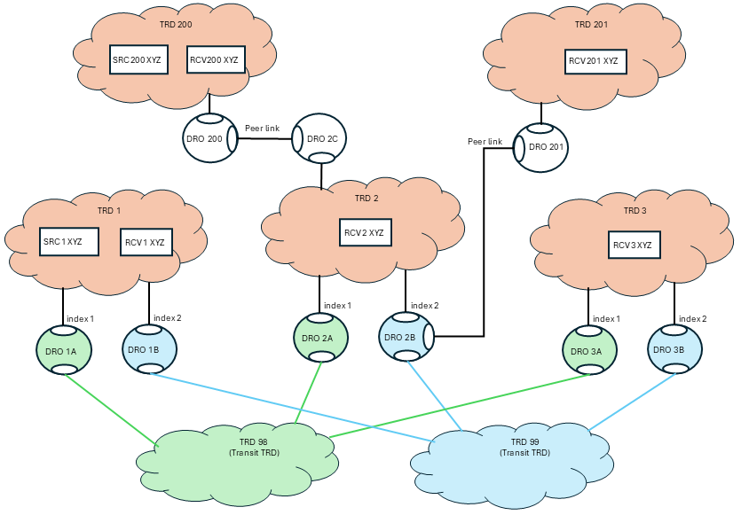
This use case acknowledges the fact that hotlinked receivers can receive double the network traffic. The advantage is high availability in the face of network failure. However, there are use cases where only a subset of "critical" topics require high availability, while normal "non-critical" topics can rely on Parallel Links with failover.
In the above diagram, TRD 1 has publishers of critical topics that end with "_crit" and other, non-critical topics that do not end with "_crit". DRO 1B is configured to only forward topics that end with "_crit" with the configuration:
<endpoint>
  ...
  <acl><inbound>
    <ace match="accept"><topic>.*_crit$</topic>
  </ace></inbound></acl>
  ...
</endpoint>
Since topic "XYZ" does not end with "_crit", DRO 1B will not forward those messages.
Now look at DROs 1A1 and 1A2. Note that they are in different route groups. Since they are configured as Parallel Links to TRD 98, they represent a hot/cold failover pair. Only one will be active, which can be controlled with Router Element "<cost>". If the active DRO fails, a failover to the inactive DRO will happen after a timeout. Topic "XYZ" will experience temporary packet loss until the failover completes.
Now note that DRO 1B is in two route groups: 1 and 2. This means that whichever of DROs 1A1 or 1A2 are active, DRO 1B will act as a hotlinked pair to it. For topics that end with "_crit", if DRO 1A1 fails, there will not be packet loss since DRO 1B is replicating the traffic for those topics.
TRD 200 is connected to TRD 2. But the connection is not with two networks, so enabling hotlinks will not significantly increase availability. To conserve bandwidth, DROs 2C and 2D are not configured with hotlink indices or route groups. Thus, 2C and 2D act as a hot/cold failover pair.
TRD 300 is connected to TRD 3 with two independent networks, but not the "main" world-wide networks embodied in transit TRDs 98 and 99. It sets up a separate pair of hotlinked DROs, DRO 3C and 3D, in route group 2 (to separate them from DROs 3A and 3B). Thus, messages published from TRD 3 can be hotlinked down to TRDs 98 and 99, and also hotlinked upward to TRD 300
- Attention
- This configuration does not provide full connectivity. Due to DRO Hotlinks Restrictions item 5, "No hotlink chains", a publisher in TRD 1 will not have its messages forwarded all the way to TRD 300, since it would have to transit two hotlinked hops. For full connectivity, TRDs 1 and 2 would also have to have hotlinked DROs connecting them to TRD 300. (Note that this restriction does not interfere with connectivity to TRD 200 - TRD 1 can reach TRD 200 by transiting only a single hotlink hop.)
Finally, note also that DROs 3A and 3B do not use transit TRDs between TRDs 3 and 300. Normally this would be done, but it was omitted to simplify the drawing.
Implementing DRO Hotlinks <-
Applications do not need special source code to make use of hotlinks. Contrast this with the Hot Failover (HF) feature that requires the use of special hot failover APIs. Hotlinks use standard source APIs (but see DRO Hotlinks Restrictions), and is enabled through source and receiver configuration, and setting up DROs.
DRO Hotlinks Restrictions <-
-
XSP deletion - If using XSPs with hotlinked receivers, no XSPs can be deleted until all receiver objects are deleted. See XSP Restrictions.
-
No Hot Failover - The hotlinks feature is not compatible with regular Hot Failover (HF). They are intended for different use cases and may not be used in the same UM network.
-
No Smart Sources - The hotlinks feature is not supported by Smart Sources.
-
Locate Stores in same TRD as source - Hotlinks supports UM's Persistence feature. However, whereas a non-hotlinked DRO network allows Stores to be placed anywhere in the network, the hotlink feature adds the restriction that the Stores must be in the same TRD as the source. Note that Informatica generally considers this restriction to be the best practice except in certain limited use cases.
-
No hotlink chains - Informatica only supports a single central redundant pair of networks using the hotlinks feature. UM does not support multiple hotlink hops (Contact UM Support for potential workarounds if this is necessary). For example, this topology is not supported:
Routing Topologies <-
You can configure multiple DROs in a variety of topologies. Following are several examples.
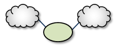
Direct Link <-
The Direct Link configuration uses a single DRO to directly connect two TRDs. For a configuration example, see Direct Link Configuration.
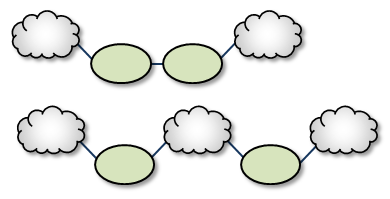
Single Link <-
A Single Link configuration connects two TRDs using a DRO on each end of an intermediate link. The intermediate link can be a "peer" link, or a transit TRD. For configuration examples, see Peer Link Configuration and Transit TRD Link Configuration.
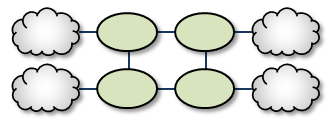
Parallel Links <-
Parallel Links offer multiple complete paths between two TRDs. However, UM will not load-balance messages across both links. Rather, parallel links are used for failover purposes. You can set preference between the links by setting the primary path for the lowest cost and standby paths at higher costs. For a configuration example, see Parallel Links Configuration.
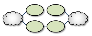
Note that if a DRO or network link fails, the failover action to the parallel DRO can take several seconds, during which time messages are not forwarded (loss). They represent a hot/cold failover pair, with only one of them active. See DRO Hotlinks for zero-loss hot/hot resilience.
Loops <-
Loops let you route packets back to the originating DRO without reusing any paths. Also, if any peer-peer links are interrupted, the looped DROs are able to find an alternate route between any two TRDs.
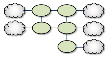
Loop and Spur <-
The Loop and Spur has a one or more DROs tangential to the loop and accessible only through a single DRO participating in the loop. For a configuration example, see Loop and Spur Configuration.
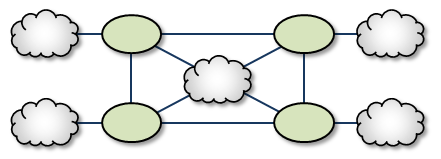
Loop with Centralized TRD <-
Adding a TRD to the center of a loop enhances its rerouting capabilities.
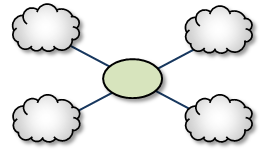
Star with centralized TRD <-
A Star with a centralized TRD does not offer rerouting capabilities but does provide an economical way to join multiple disparate TRDs.
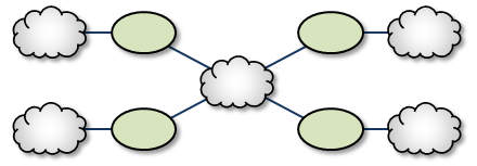
Star with Centralized DRO <-
The Star with a centralized DRO is the simplest way to bridge multiple TRDs. For a configuration example, see Star Configuration.
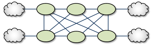
Mesh <-
The Mesh topology provides peer portal interconnects between many DROs, approaching an all-connected-to-all configuration. This provides multiple possible paths between any two TRDs in the mesh. Note that this diagram is illustrative of the ways the DROs may be interconnected, and not necessarily a practical or recommended application. For a configuration example, see Mesh Configuration.
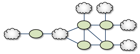
Palm Tree <-
The Palm Tree has a set of series-connected TRDs fanning out to a more richly meshed set of TRDs. This topology tends to pass more concentrated traffic over common links for part of its transit while supporting a loop, star, or mesh near its terminus.
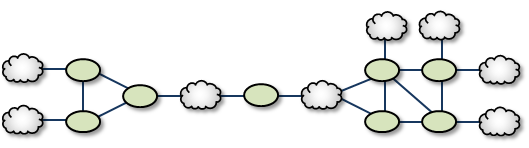
Dumbbell <-
Similar to the Palm Tree, the Dumbbell has a funneled route with a loop, star, or mesh topology on each end.
Unsupported Configurations <-
When designing DRO networks, do not use any of the following topology constructs.
Two peer-to-peer connections between the same two DROs:

Two endpoint connections from the same DRO to the same TRD:

Assigning two different Domain ID values (from different DROs) to the same TRD:

UM Feature Compatibility <-
You must install the UM Dynamic Routing Option with its companion Ultra Messaging UMS, UMP, or UMQ product, and versions must match. While most UM features are compatible with the DRO, some are not. Following is a table of features and their compatibilities with the DRO.
| UM Feature | DRO Compatible? | Notes |
|---|---|---|
| Connect and Disconnect Source Events | Yes, but see Source Connect and Disconnect Events | |
| Hot Failover (HF) | Yes | The DRO can pass messages sent by HF publishers to HF receivers, however the DRO itself cannot be configured to originate or terminate HF data streams. |
| Hot Failover Across Multiple Contexts (HFX) | Yes | |
| Late Join | Yes | |
| Message Batching | Yes | |
| Monitoring/Statistics | Yes | |
| Multicast Immediate Messaging (MIM) | Yes | |
| Off-Transport Recovery (OTR) | Yes | |
| Ordered Delivery | Yes | |
| Pre-Defined Messages (PDM) | Yes | |
| Request/Response | Yes | |
| Self Describing Messaging (SDM) | Yes | |
| Smart Sources | Partial | The DRO does not support proxy sources sending data via Smart Sources. The DRO does accept ingress traffic to proxy receivers sent by Smart Sources. |
| Source Side Filtering | Yes | The DRO supports transport source side filtering. You can activate this either at the originating TRD source, or at a downstream proxy source. |
| Source String | Yes, but see Source Strings in a Routed Network | |
| Transport Acceleration | Yes | |
| Transport LBT-IPC | Yes | |
| Transport LBT-RM | Yes | |
| Transport LBT-RU | Yes | |
| Transport LBT-SMX | Partial | The DRO does not support proxy sources sending data via LBT-SMX. Any proxy sources configured for LBT-SMX will be converted to TCP, with a log message warning of the transport change. The DRO does accept LBT-SMX ingress traffic to proxy receivers. |
| Transport TCP | Yes | |
| Transport Services Provider (XSP) | No | |
| JMS, via UMQ broker | No | |
| Spectrum | Yes | The DRO supports UM Spectrum traffic, but you cannot implement Spectrum channels in DRO proxy sources or receivers. |
| UMP Implicit and Explicit Acknowledgments | Yes | |
| UMP Persistent Store | Yes | |
| UMP Persistence Proxy Sources | Yes | |
| UMP Quorum/Consensus Store Failover | Yes | |
| UMP Managing RegIDs with Session IDs | Yes | |
| UMP RPP: Receiver-Paced Persistence (RPP) | Yes | |
| UMQ Brokered Queuing | No | |
| UMQ Ultra Load Balancing (ULB) | No | |
| Ultra Messaging Desktop Services (UMDS) | Not for client connectivity to the UMDS server | |
| Ultra Messaging Manager (UMM) | Yes | Not for DRO management |
| UM SNMP Agent | No | |
| UMCache | No | |
| UM Wildcard Receivers | Yes | |
| Zero Object Delivery (ZOD) | Yes |
DRO Implementation <-
DRO Configuration Overview <-
When the DRO daemon launches, it uses configuration option settings to determine its behavior and expectations. You specify option values in an XML configuration file, and reference the file from a command line argument.
Typically, you have a separate XML configuration file for each DRO, which contains structured configuration elements that describe aspects of the DRO. Within this XML configuration file, each endpoint portal definition points to a UM configuration file, which allow the portal to properly connect to its TRD.
Creating Applications for DRO Compatibility <-
When developing messaging applications that use Ultra Messaging and, in particular, the DRO, please observe the following guidelines.
Naming and Identification <-
An important part to successfully implementing DROs is prudent and error-free naming of TRDs, DROs, portals, etc., as well as correct identification of IP addresses and ports. It is good practice to first design the DRO network by defining all connections and uniquely naming all DROs, portals, and TRDs. This works well as a diagram similar to some examples presented in this document. Include the following names and parameters in your design diagram:
- TRD names and IDs
- DRO names
- Portal names
- Portal costs
For example, a well-prepared DRO design could look like the following figure.
Portal Costs <-
A network of DROs uses forwarding cost as the criterion for determining the best (lowest cost) path over which to resolve a topic and route data. Forwarding cost is simply the sum of all portal costs along a multi-DRO path. Thus, total cost for the single path in the above example is 34. (Note that this is a non-real-world example, since costs are pointless without alternate routes to compare to.) You assign portal costs via the <cost> configuration option.
After the DRO network calculates its paths, if a new lower-cost source becomes available, receivers switch to that path.
Access Control Lists (ACL) <-
In the DRO, an Access Control List (ACL) is a method of blocking traffic from being forwarded from one TRD to another.
Typical applications for this feature are:
- Prevent unauthorized access to sensitive messages.
- Prevent overloading of bandwidth-limited WAN links, even in the face of accidental use of overly-permissive wildcard receivers.
- ACLs can be used to limit the amount of Topic Resolution traffic for topics on TRDs that don't need those topics. However, the use of wildcard receivers can result in TR traffic even for topics which are blocked from being forwarded.
You can apply Access Control Lists to one or more of a DRO's portals to filter traffic by topic, transport, transport session, etc. You configure an ACL in a DRO's XML configuration's <acl> element, as a child of an <endpoint> or <peer> portal. As messages are processed by the DRO, the portals use the ACLs to decide whether to reject the the messages or accept them.
Inbound vs. Outbound
There are two types of ACLs: inbound and outbound.
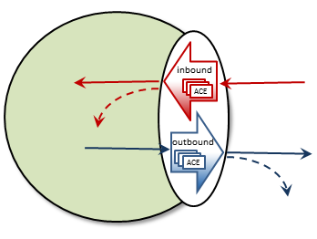
An inbound ACL tests messages from a source TRD on their way into a DRO portal, and decides whether to reject or accept them. If accepted, the messages can be forwarded to the appropriate destination portal(s).
An outbound ACL tests messages on their way out of a DRO portal, and decides whether to reject them, or transmit them to the destination TRD.
This distinction becomes especially important when a DRO has more than two portals. Messages rejected inbound cannot be forwarded at all. Messages rejected outbound can allow messages to be forwarded out some portals but not others.
An ACL contains one or more Access Control Entries (ACEs).
Access Control Entry (ACE)
An ACE specifies a set of message matching criteria, and an action to perform based on successful matches. The action is either accept (the message is made available for forwarding, based on interest) or reject (the message is dropped).
When more than one ACE is supplied in an ACL, messages are tested against each ACE in the order defined until a match is found, at which point the ACE specifies what to do (reject or accept).
An ACE contains one or more conditional elements.
Conditional Elements
Conditional elements do the work of testing various characteristics of messages to determine if they should be rejected or accepted (made available for forwarding).
When more than one conditional element is supplied in an ACE, received messages are tested against all of them to determine if the ACE should be applied.
There are two classes of conditional elements:
- Topic conditionals, which test the topic string of a message.
- Transport session conditionals, which test network transport session characteristics of a message.
Topic conditionals can be included on both inbound and outbound ACLs. The topic conditionals are:
- <topic> - tests for a specific topic name of messages,
- <pcre-pattern> - matches a group of topics according to a regular expression pattern,
- <regex-pattern> - deprecated, use <pcre-pattern> instead.
Transport session conditionals only apply to inbound ACLs (they are ignored for outbound). The transport session conditionals are:
- <transport> - tests the transport type of messages.
- <source-ip> - tests the IP address of the source or proxy source of messages.
- <multicast-group> - tests the destination multicast group of LBT-RM messages.
- <udp-destination-port> - tests the destination port of LBT-RM messages.
- <udp-source-port> - tests the source port of LBT-RM and LBT-RU messages.
- <tcp-source-port> - tests the source port of TCP messages.
- <xport-id> - tests the transport ID of LBT-IPC messages.
Conditional elements are children of the <ace> element. If you place multiple conditions within an ACE, the DRO performs an "and" operation with them. That is, all relevant conditions in the ACE must be true for the ACE to be applied to a message.
A portal will silently ignore conditional elements that don't apply. For example, if a transport conditional is used on an outbound ACL, or if a UDP-based conditional is present and a TCP message is received.
Reject by Default
An implicit "reject all" is at the end of every ACL, so the DRO rejects any topic not matched by any ACE. When an ACL is configured for a portal, rejection is the default behavior.
For example, to accept and forward only messages for topic ABC and reject all others:
No "reject" ACE is needed since rejection is the default.
In contrast, to accept all messages except for topic ABC:
The second ACE is used as a "match all", which effectively changes the default behavior to "accept".
ACE Ordering
Since the behavior for multiple ACEs is to test them in the order defined, ACEs should be ordered from specific to general.
In the example below, a user named "user1" is assigned to the LAN1 TRD. It is desired to forward all non-user-specific messages, but restrict user-specific message to only that user.
By ordering the ACEs as shown, messages for USER.user1 will be forwarded by the first ACE, but messages for USER.user2, etc. will be rejected due to the second ACE. Messages for topics not starting with "USER." will be forwarded by the third ACE.
Note that the string in "<topic>USER.user1</topic>" is not a regular expression pattern, and therefore does not need any special escaping or meta characters. The "<pcre-pattern>^USER\..*</pcre-pattern>" is a regular expression, and therefore needs the "^" anchor and the "\." escape sequence.
Timers and Intervals <-
The DRO offers a wide choice of timer and interval options to fine tune its behavior and performance. There are interactions and dependencies between some of these, and if misconfigured, they may cause race or failure conditions.
This manual's description of configuration options (see DRO Configuration Reference), includes identification of such relationships. Please heed them.
Multicast Immediate Messaging Considerations <-
Multicast Immediate Messages (MIMs) may pass through the DRO. You cannot filter MIMs with Access Control Lists (ACL)-MIMs are forwarded to all TRDs. Informatica does not recommend using MIM for messaging traffic across the DRO. MIM is intended for short-lived topics and applications that cannot tolerate a delay between source creation and the sending of the first message. See also Multicast Immediate Messaging.
Persistence Over the DRO <-
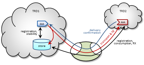
The DRO supports UMP persistence by routing all necessary control and retransmission channels along with transport and topic resolution traffic. A typical implementation places the UMP persistent store in the same TRD as its registered source, as shown in the following figure.
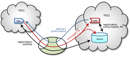
The DRO also supports UMP implementations with the store located in a receiver's TRD, as shown in the following figure.
Note: For more reliable operation when using UMP with DROs, Informatica recommends enabling OTR.
Late Join and Off-Transport Recovery <-
The DRO supports sources and receivers configured for Late Join and/or Off-Transport Recovery (OTR). Retransmission requests and subsequent retransmissions are conducted across the entire path through the DRO network. A DRO's proxy sources do not have Late-Join/OTR retention buffers and hence, are not able to provide recovered messages.
Topic Resolution Reliability <-
Topic resolution can sometimes remain in a quiescent phase due to link interruption, preventing needed re-subscription topic resolution activity. Two ways you can address this are:
- For isolated incidents, call lbm_context_topic_resolution_request() (see example lbmtrreq.c). This restarts the sustaining phase.
- For more chronic problems, such as a DRO link (especially an endpoint link) over a WAN of questionable reliability, consider configuring Topic resolution to stay in the sustaining phase (options resolver_advertisement_minimum_sustain_duration (source) and resolver_query_minimum_sustain_duration (receiver)).
BOS and EOS Behavior Over the DRO <-
Through a network of DROs, a topic traverses a separate session for each link along its path. Thus, the DRO reports BOS/EOSs based on the activity between the proxy source transport and its associated receiver. There is no end-to-end, application-to-application reporting of the data path state. Also, in the case of multiple topics being assigned to multiple sessions, topics may find themselves with different session mates from hop to hop. Of course, this all influences when, and for which transport session, a topic's BOSs and EOSs are issued.
DRO Reliable Loss <-
The DRO can create a situation where a "reliable" transport (TCP or LBT-IPC) can experience out-of-order message delivery.
The DRO can perform a "protocol conversion" function. I.e. an originating source can use a UDP-based protocol (LBT-RM or LBT-RU), but the proxy source for a remote receiver can use a "reliable" protocol (TCP or LBT-IPC). With a UDP-based protocol, messages can arrive to the DRO network out of order, usually due to packet loss and recovery. However, when those out-of-order messages are forwarded across a "reliable" protocol (TCP or LBT-IPC), the receiver does not expect the sequence number gap, and immediately declares the out-of-order messages as unrecoverable loss. This, in spite of the fact that the missing message arrives shortly thereafter.
Starting in UM version 6.12, there are two new configuration options: transport_tcp_dro_loss_recovery_timeout (receiver) and transport_lbtipc_dro_loss_recovery_timeout (receiver), which modify the receiver's behavior. Instead of declaring a gap immediately unrecoverable, a delay is introduced which is similar to what a UDP-based receiver uses to wait for lost and retransmitted datagrams. If the missing message arrives within the delay time, the messages are delivered to application without loss.
Be aware that this functionality is only used with "reliable" protocols published by a DRO's proxy source. If this delay feature is enabled, it will not apply to a "reliable" protocol that is received directly from the originating source.
Note however that you can get genuine gaps in the "reliable" data stream without recovery. For example, an overloaded DRO can drop messages. Or a DRO's proxy receiver can experience unrecoverable loss. In that case, the delay will have to expire before the missing messages are declared unrecoverable and subsequent data is delivered.
- Attention
- The delay times default to 0, which retains the pre-6.12 behavior of immediately declaring sequence number gaps unrecoverable. If you want this new behavior, you must configure the appropriate option.
Topology Configuration Examples <-
Following are example configurations for a variety of DRO topologies. These are the topology examples presented Routing Topologies.
In a real-world situation, you would have DRO XML configuration files with their portal interfaces referencing complete UM configuration files. However, for these examples, the referred domain configuration files are simplified to contain only information relevant to the applicable DRO. As part of this simplification, domain configuration files show interfaces for only one or two transport types.
Also, IP addresses are provided in some cases and omitted in other cases. This is because initiator peer portals need to know the IP addresses (and port numbers) of their corresponding acceptor portals to establish connections, whereas endpoint portals communicate via topic resolution and thus, do not need to know IP addresses.
- Note
- Before designing any DRO implementations based on configurations or examples other than the types presented in this document, please contact UM Support.
Direct Link Configuration <-
This example uses a DRO to connect two topic resolution domain LANs.
TRD1 Configuration
This UM configuration file, trd1.cfg, describes TRD1 and is referenced in the DRO configuration file.
G1 Configuration
This DRO configuration file defines two endpoint portals. In the daemon section, we have turned on monitoring for the all endpoint portals in the DRO. The configuration specifies that all statistics be collected every 5 seconds and uses the lbm transport module to send statistics to your monitoring application, which runs in TRD1. See also UM Concepts, Monitoring UMS. The Web Monitor has also been turned on (port 15304) to monitor the performance of the DRO.
TRD2 Configuration
The configuration file trd2.cfg could look something like this.
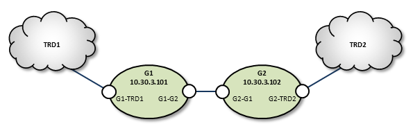
Peer Link Configuration <-
In cases where the DRO connection between two TRDs must tunnel through a WAN or TCP/IP network, you can implement a DRO at each end, as shown in the example below.
TRD1 Configuration
G1 Configuration
Following is an example of two companion peer portals (on different DROs) configured via DRO XML configuration file for a TCP-only setup. Note that one must be an initiator and the other, an acceptor.
G2 Configuration
TRD2 Configuration
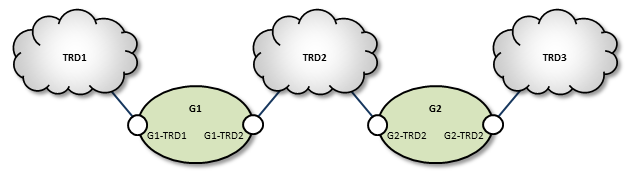
Transit TRD Link Configuration <-
This example, like the previous one, configures two localized DROs tunneling a connection between two TRDs, however, the DROs in this example are tunneling through an intermediate TRD. This has the added effect of connecting three TRDs.
TRD1 Configuration
G1 Configuration
Following is an example of two companion peer portals (on different DROs) configured via DRO XML configuration file for a TCP-only setup. Note that one must be an initiator and the other, an acceptor.
TRD2 Configuration
G2 Configuration
TRD3 Configuration
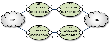
Parallel Links Configuration <-
This example is similar in purpose to the single link, peer-to-peer example, except that a second pair of DROs is added as a backup route. You can set one of these as a secondary route by assigning a higher cost to portals along the path. In this case we set G3 and G4's portal costs to 5, forcing the lower route to be selected only if the upper (G1, G2) route fails.
Also note that we have configured the peer portals for the leftmost or odd-numbered DROs as initiators, and the rightmost or even-numbered DRO peers as acceptors.
TRD1 Configuration
G1 Configuration
G2 Configuration
G3 Configuration
G4 Configuration
TRD2 Configuration
Loop and Spur Configuration <-
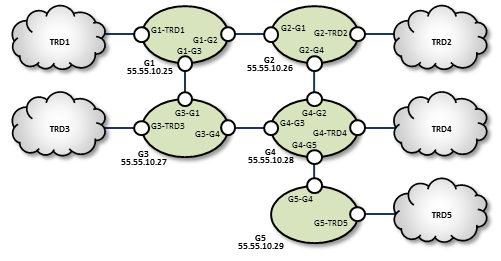
TRD1 Configuration
G1 Configuration
G2 Configuration
TRD2 Configuration
TRD3 Configuration
G3 Configuration
G4 Configuration
TRD4 Configuration
G5 Configuration
TRD5 Configuration
Star Configuration <-
This network consists of four TRDs. Within each TRD, full multicast connectivity exists. However, no multicast connectivity exists between the four TRDs.
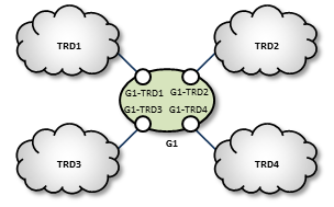
G1 Configuration
The configuration for this DRO also has transport statistics monitoring and the WebMonitor turned on.
TRD1 Configuration
TRD2 Configuration
TRD3 Configuration
TRD4 Configuration
Mesh Configuration <-
The mesh topology utilizes many connections between many nodes, to provide a variety of alternate routes. However, meshes are not the best solution in many cases, as unneeded complexity can increase the chance for configuration errors or make it more difficult to trace problems.
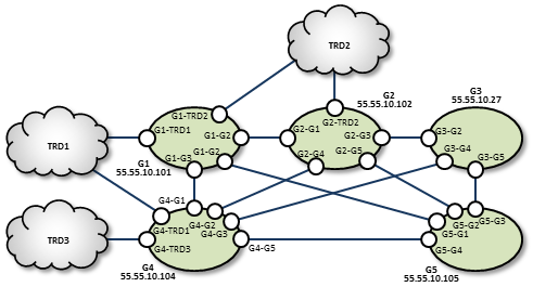
TRD1 Configuration
G1 Configuration
G2 Configuration
G3 Configuration
TRD2 Configuration
TRD3 Configuration
G4 Configuration
G5 Configuration
Using UM Configuration Files with the DRO <-
Within the DRO configuration file, the endpoint portal's <lbm-config> element lets you import configurations from either a plain text or XML UM configuration file. However, using the XML type of UM configuration files provides the following advantages over plain text UM configuration files:
- You can apply UM attributes per topic and/or per context.
- You can apply attributes to all portals on a particular DRO using a UM XML template (instead of individual portal settings).
-
Using UM XML templates to set options for individual portals lets the DRO process these settings in the
<daemon>element instead of within each portal's configuration.
Setting Individual Endpoint Options <-
When setting endpoint options, first name the context of each endpoint in the DRO's XML configuration file.
Then assign configuration templates to those contexts in the UM XML configuration file.
You specify the unique options for each of this DRO's two endpoints in the UM XML configuration <templates> section used for G1-E1-options and G1-E2-options.
DRO and UM XML Configuration Use Cases <-
One advantage of using UM XML configuration files with the DRO is the ability to assign unique UM attributes to the topics and contexts used for the proxy sources and receivers (which plain text UM configuration files cannot do). The following example shows how to assign a different LBTRM multicast address to a source based on its topic.
Create a new UM XML configuration template for the desired topic name.
Then include this template in the <application> element associated with the DRO.
It is also possible to assign UM attributes directly in the <application> tag. For example, the following specifies that a particular topic should use an LBT-RU transport.
Sample Configuration <-
The following sample configuration incorporates many of the examples mentioned above. The DRO applies options to all UM objects created. The UM XML configuration file overwrites these options for two specific topics. The first topic, LBTRM_TOPIC, uses a different template to change its transport from TCP to LBTRM, and to set an additional property. The second topic, LBTRU_TOPIC, also changes its transport from TCP to a new value. However, its new attributes are applied directly in its associated topic tag, instead of referencing a template. In addition, this sample configuration assigns the rm-source template to all sources and receivers associated with the context endpt_1.
XML UM Configuration File <-
XML DRO Configuration File <-
This DRO uses the above XML UM configuration file, sample-config.xml, to set its UM options. It has three endpoints, one of which has the context endpt_1.
Running the DRO Daemon <-
To run the DRO, ensure the following:
- Library environment variable paths are set correctly (LD_LIBRARY_PATH)
- The license environment variable LBM_LICENSE_FILENAME points to a valid DRO license file.
- The configuration file is error free.
Typically, you run the DRO with one configuration file argument, for example:
(FYI: "tnwgd" stands for "Twenty Nine West Gateway Daemon", a historical name for the DRO.)
The DRO logs version information on startup. The following is an example of this information:
DRO NAT Transit <-
Some networks make use of a NAT router to map one IP address space onto another. If your network architecture includes LANs that are bridged with a NAT device, UM receivers will usually not be able to connect directly to UM sources across the NAT. Sources send Topic Resolution advertisements containing their local IP addresses and ports, but receivers on the other side of the NAT cannot access those sources using those local addresses/ports. They must use alternate addresses/ports, which the NAT forwards according to the NAT's configuration.
The recommended method of transiting a NAT is using two DROs connected via a peer link. The UM components in one network are organized as one TRD and the components in the other network are organized as a separate TRD.
There is an alternative method of transiting a NAT with UM using an lbmrd. This method reduces latency but has significant restrictions.
DRO NAT: TCP Peer <-
The simplest way to transit a NAT is to configure the DROs with Router Element "<single-tcp>". One DRO is configured to be the initiator and the other is the acceptor.
Many NAT designs restrict which network can initiate TCP connections across the NAT. The initiator DRO should be placed on the side that supports outgoing connections and configured for the IP address and port that the NAT router recognizes and forwards to the acceptor DRO. This may or may not be the IP address and port of the actual host running the acceptor DRO; contact your network support group for details.
DRO NAT: UDP Peer <-
DROs are sometimes configured to add UDP-based data transport. The TCP link is still used for command and control, so all the points made above still apply. In addition, the NAT must allow forwarding of bi-directional UDP traffic without modifying the destination port numbers.
Here's the sequence of events UM uses to establish communication:
-
The initiator DRO uses the configured address:port to initiate its TCP connection. Once established, the initiator sends DRO the UDP port it's accepting data on.
-
The acceptor DRO accepts the TCP connection, saves the UDP port of the initiator, and sends back it's own UDP port. The acceptor also examines the established TCP connection to determine the IP address of the initiator, and saves that. But note that due to the NAT, the IP address it determines will typically not be the initiator's host IP. Rather, it's an IP address of the NAT device, and the NAT will forward packets to the actual host running the initiator.
-
The initiator receives the acceptor's UDP port and saves it.
-
Now, when the initiator wants to send UDP data to the acceptor, it uses the configured IP and the saved UDP port as the UDP packet's destination IP/port.
- When the acceptor wants to send UDP data to the initiator, it uses the saved IP and UDP port.
Thus, for both the initiator and the acceptor, the configured UDP port is both used to locally bind the UDP socket, and used by the remote DRO as the UDP destination port. Thus, the NAT must not modify the destination port of UDP packets.
Some NAT designs do not expect this UDP behavior. Rather they perform a similar form of dynamic port allocation where a packet's source port is modified, and the networking software is expected to examine the source port and use it for outgoing packets. UM does not do that.
The NAT should be configured with static port mappings for all DRO peer links expected. If this is not practical, then UDP peer links may not be usable. Contact UM Support.
DRO Monitoring <-
See Monitoring for an overview of monitoring an Ultra Messaging network.
It is important to the health and stability of a UM network to monitor the operation of DROs (if any). This monitoring should include real-time automated detection of problems that will produce a timely alert to operations staff.
Three types of data should be monitored:
- Log file.
- UM library statistics (context, source, receiver, wildcard receiver, event queue).
- Daemon statistics (similar data to the DRO Web Monitor).
For UM library stats and daemon stats, the monitoring messages contain an "application ID". For UM applications, this is a user-specified name intended to identify the individual component/instance, and is supplied by the option monitor_appid (context).
However, in the DRO, the application ID is NOT controlled by the "monitor-appid" option, and is instead used to identify not only the specific DRO, but also the portal within the DRO that is supplying the stats.
In the case of the DRO's daemon stats, the application ID is set to the Router Element "<name>" located within the Router Element "<daemon>". For example, a DRO configured with:
The daemon stats will have the application ID "dro1".
In the case of UM library stats (context, transport, event queue), the application ID is constructed as follows:
Gateway_Portal_portalname_portalcontext
Where portalname is set to the Router Element "<name>" located within the Router Element "<endpoint>", and portalcontext is set to either "rcv_ctx" or "src_ctx". For example, a DRO configured with:
The UM library stats will have the application ID "Gateway_Portal_TRD1_rcv_ctx" and "Gateway_Portal_TRD1_src_ctx".
DRO Monitoring: Logs <-
Ideally, log file monitoring would support the following:
- Archive all log messages for all DROs for at least a week, preferably a month.
- Provide rapid access to operations staff to view the latest log messages from a DRO.
- Periodic scans of the log file to detect errors and raise alerts to operations staff.
Regarding log file scanning, messages in the DRO's log file contain a severity indicator in square brackets. For example:
[2022-11-01 13:28:51.720796] [information] Gwd-9574-01: RecalcTrigger:LINK CAME UP:Version = 1:NodeId = 1
Informatica recommends alerting operations staff for messages of severity [WARNING], [ERROR], [CRITICAL], [ALERT], and [EMERGENCY].
It would also be useful to have a set of exceptions for specific messages you wish to ignore.
There are many third party real-time log file analysis tools available. A discussion of possible tools is beyond the scope of UM documentation.
DRO Monitoring: UM Library Stats <-
The DRO communicates with applications using Ultra Messaging protocols, and therefore makes use of the UM library. It is just as important to monitor the UM library statistics for the DRO as it is for applications.
There are two data formats for UM library stats:
- Protobufs - recommended.
- CSV - deprecated. Informatica recommends migrating to protobufs.
For example, here is an excerpt from a sample DRO configuration file that shows how automatic monitoring is enabled:
Here is an excerpt from a sample "um.xml":
Notes:
-
The Router Element "<format-module>" value "pb" selects the protobuf format and is available for the DRO in UM version 6.14 and beyond. Selecting this format implicitly enables the inclusion of the DRO's daemon stats (see below).
-
For a list of possible protobuf messages for the DRO, see the "dro_mon.proto" file at Example dro_mon.proto.
-
The Router Element "<monitor>" enables automatic monitoring and defines the statistics sampling period. In the above example, 600 seconds (10 minutes) is chosen somewhat arbitrarily. Shorter times produce more data, but not much additional benefit. However, UM networks with many thousands of applications may need a longer interval (perhaps 30 or 60 minutes) to maintain a reasonable load on the network and monitoring data storage.
-
When automatic monitoring is enabled, it creates a context named "29west_statistics_context". It is configured with the "mon_ctx" template, which sets options for the monitoring data TRD. (Alternatively, you can configure the monitoring context using monitor_transport_opts (context).) When possible, Informatica recommends directing monitoring data to an administrative network, separate from the application data network. This prevents monitoring data from interfering with application data latency or throughput. In this example, the monitoring context is configured to use an interface matching
10.29.3.0/24. -
In this example, the monitoring data TRD uses Unicast UDP Topic Resolution. The lbmrd daemon is running on host 10.29.3.101, port 12001.
-
The monitoring data is sent out via UM using the TCP transport.
-
These settings were chosen to conform to the recommendations in Automatic Monitoring.
For a full demonstration of monitoring, see: https://github.com/UltraMessaging/mcs_demo
DRO Monitoring: Daemon Stats <-
The daemon statistics for the DRO represent a superset of the information presented on the DRO Web Monitor.
There are two data formats for the DRO to send its daemon stats:
- Protobufs - recommended.
- Binary - deprecated. Informatica recommends migrating to protobufs. For information on the deprecated binary formatted daemon stats, see DRO Binary Daemon Statistics.
The recommended way to enable DRO daemon stats is by enabling UM library stats using the DRO's <monitor> element with <format-module module="pb">. For example, here's an excerpt from a DRO configuration file from https://github.com/UltraMessaging/mcs_demo file um.xml:
    <monitor interval="600">
      <transport-module module="lbm"/>
      <format-module module="pb"/>
    </monitor>
The protobufs format is accepted by the Monitoring Collector Service (MCS) and the "lbmmon" example applications: Example lbmmon.c and Example lbmmon.java.
For a list of possible protobuf messages for the DRO, see the "dro_mon.proto" file at Example dro_mon.proto.
For a full demonstration of monitoring, including DRO daemon stats, see: https://github.com/UltraMessaging/mcs_demo
See also DRO Monitoring: UM Library Stats.
DRO Web Monitor <-
- Note
- The DRO web monitor functionality is deprecated in favor of MCS. We do not plan to remove existing web monitor functionality, and will continue to support it in its current state. But we do not plan to enhance the web monitor in the future.
The built-in web monitor (configured in the tnwgd XML configuration file; see DRO Configuration Reference) provides valuable statistics about the DRO and its portals, for which, the Web Monitor separates into receive statistics and send statistics. The Web Monitor provides a page for each endpoint and peer portal.
- Warning
- The DRO's web monitor is not designed to be a highly-secure feature. Anybody with access to the network can access the web monitor pages.
Users are expected to prevent unauthorized access to the web monitor through normal firewalling methods. Users who are unable to limit access to a level consistent with their overall security needs should disable the DRO web monitor (using <web-monitor>). See Webmon Security for more information.
Main Page <-
This page displays general information about the DRO, and also provides the following links to more detailed statistical and configuration information.
- UM Router Configuration
- Displays the DRO XML configuration file used by this DRO.
- Portals
- Displays portal statistics and information, one portal per page. The Portals page allows you to link to any of the Peer or Endpoint portals configured for the DRO.
- Topology Info
- This links to a page that displays DRO network connectivity information from the perspective of this DRO.
- Path Info
- This lets you query and display a hop path that messages will take between any two TRDs.
On some platforms, the Main page may include a link (GNU malloc info) to a memory allocation display page that displays the following:
- arena
- Non-mmapped space allocated (bytes)
- ordblks
- Number of free chunks
- hblks
- Number of mmapped regions
- hblkhd
- Space allocated in mmapped regions (bytes)
- uordblks
- Total allocated space (bytes)
- fordblks
- Total free space (bytes)
Endpoint Portal Page <-
The Endpoint Portal Page displays Receive and Send statistics for the selected endpoint portal. Receive statistics pertain to messages entering the portal from its connected TRD. Send statistics pertain to messages sent out to the TRD.
Click on any of the links at the top of the page to review configuration option values for the portal's UM topic resolution domain. The two columns provide different units of measure for a given statistic type, where the first column is typically in fragments or messages (depending on the statistic type), and the second column is in bytes.
Endpoint Portal name
- Domain ID
- The ID for the Topic Resolution Domain (TRD) to which this portal is connected.
- Portal Cost
- The cost value assigned to this portal.
- Local Interest
- Totals (listed below) for topics and patterns in this portal's interest list that originated from receivers in the immediately adjacent TRD.
- Topics
- Of the local interest total, the number of topics.
- PCRE patterns
- Of the local interest total, the number of wildcard patterns, using PCRE pattern matching.
- REGEX patterns
- Of the local interest total, the number of wildcard patterns, using REGEX pattern matching.
- Remote Interest
- Totals (listed below) for topics and patterns in this portal's interest list that originated from receivers beyond and downstream from the immediately adjacent TRD.
- Topics
- Of the remote interest total, the number of topics.
- PCRE patterns
- Of the remote interest total, the number of wildcard patterns, using PCRE pattern matching.
- REGEX patterns
- Of the remote interest total, the number of wildcard patterns, using REGEX pattern matching.
- Proxy Receivers
- The number of proxy receivers active in this portal.
- Receiver Topics
- The number of topics in which the other portals in the DRO have detected current interest and summarily propagated to this portal.
- Receiver PCRE patterns
- The number of wildcard patterns, using PCRE pattern matching, in which the other portals in the DRO have detected current interest and summarily propagated to this portal.
- Receiver REGEX patterns
- The number of wildcard patterns, using REGEX pattern matching, in which the other portals in the DRO have detected current interest and summarily propagated to this portal.
- Proxy Sources
- The number of proxy sources active in this portal.
Endpoint Receive Statistics
- Transport topic fragments/bytes received
- The total transport-based topic-related traffic of messages containing user data received by this portal from a TRD. The first column counts the number of fragments (or whole messages for messages that were not fragmented).
- Transport topic request fragments/bytes received
- Topic messages received that are request messages, i.e., messages send via lbm_send_request*() rather than lbm_src_send*().
- Transport topic control msgs/bytes received
- The total transport-based topic-related traffic received by this portal from a TRD. These are supervisory messages, which include TSNIs, SRIs., etc. The first column counts the number of messages.
- Immediate topic fragments/bytes received
- The total number of Multicast Immediate Messaging (MIM) messages or message fragments, and bytes (second column), that have a topic, received at this portal.
- Immediate topic request fragments/bytes received
- Of the MIM topic messages received, this is the amount of those that are requests.
- Immediate topicless fragments/bytes received
- The total number of MIM messages or message fragments, and bytes (second column), with null topics, received by his portal.
- Immediate topicless request fragments/bytes received
- Of the MIM topicless messages received, this is the amount of those that are requests.
- Unicast data messages/bytes received
- The total number of Unicast Immediate Messaging (UIM) messages (and bytes, second column) containing user data, received by this portal.
- Duplicate unicast data messages/bytes dropped
- UIM data messages discarded because they were duplicates of messages already received.
- Unicast data messages/bytes received with no stream info
- UIM data messages discarded because they were from an earlier, incompatible version of UM. This counter should stay at 0; otherwise, contact UM Support.
- Unicast data messages/bytes received with no route to destination
- UIM data messages that are on a wrong path, possibly due to a route recalculation. This counter should stay at 0, though it may increment a few messages at the time of a topology change.
- Unicast control messages/bytes received
- The total number of Unicast Immediate Messaging (UIM) supervisory (non-data) messages (and bytes, second column) received by this portal.
- Duplicate unicast control messages/bytes dropped
- Supervisory UIMs dropped because they were duplicates of messages already received.
- Unicast control messages/bytes received with no stream info
- Supervisory UIMs dropped because they were from an earlier, incompatible version of UM. This counter should stay at 0; otherwise, contact UM Support.
- Unicast control messages/bytes received with no route to destination
- Supervisory UIM messages that are on a wrong path, possibly due to a route recalculation. This counter should stay at 0, though it may increment a few messages at the time of a topology change.
Endpoint Send Statistics
- Transport topic fragments/bytes forwarded
- The total transport-based topic-related traffic forwarded to this portal from other portals in this DRO. This could include user messages, TSNIs, SRIs, etc. The first column counts the number of fragments (or whole messages for messages that were not fragmented).
- Transport topic fragments/bytes sent
- Of the transport topic traffic forwarded, this is the amount of traffic sent out to the TRD.
- Transport topic request fragments/bytes sent
- Of the messages sent, this is the amount of those that are requests.
- Duplicate transport topic fragments/bytes dropped
- Of the messages forwarded to this portal, this is the total of those that were discarded because they were duplicates of messages already received.
- Transport topic fragments/bytes dropped due to blocking
- Of the messages forwarded to this portal, this is the amount of those that were discarded because they were blocked from sending, and were unable to be buffered. Message rates on other portals probably exceeded the rate controller limit on this portal.
- Transport topic fragments/bytes dropped due to error
- Of the messages forwarded to this portal, this is the total of those that were discarded due to an application or network connection failure.
- Transport topic fragments/bytes dropped due to fragment size error
- Of the messages forwarded to this portal, this is the total of those that were discarded possibly because of a configuration error. If this count is not at or near 0, verify that maximum datagram size for all transports is the same throughout the network.
- Immediate topic fragments/bytes forwarded
- The total number of Multicast Immediate Messaging (MIM) messages or message fragments, and bytes (second column), forwarded to this portal from other portals in this DRO.
- Immediate topic fragments/bytes sent
- Of the MIM topic messages forwarded to this portal, this is the amount of traffic sent out to the TRD.
- Immediate topic request fragments sent
- Of the MIM topic messages sent, this is the amount of those that are requests.
- Immediate topic fragments/bytes dropped due to blocking
- Of the MIM topic messages forwarded to this portal, this is the amount of those that were discarded because they were blocked from sending, and were unable to be buffered. Message rates on other portals probably exceeded the rate controller limit on this portal.
- Immediate topic fragments/bytes dropped due to error
- Of the MIM topic messages forwarded to this portal, those that were discarded due to an application or network connection failure.
- Immediate topic fragments/bytes dropped due to fragment size error
- Of the MIM topic messages forwarded to this portal, those that were dropped possibly because of a configuration error. If this count is not at or near 0, verify that maximum datagram size for all transports is the same throughout the network.
- Immediate topicless fragments/bytes forwarded
- The total number of Multicast Immediate Messaging (MIM) messages or message fragments, and bytes (second column), with null topics, forwarded to this portal from other portals in this DRO.
- Immediate topicless fragments/bytes sent
- Of the MIM topicless messages forwarded to this portal, this is the amount of traffic sent out to the TRD.
- Immediate topicless request fragments sent
- Of the MIM topicless messages sent, this is the amount of those that are requests.
- Immediate topicless fragments/bytes dropped due to blocking
- Of the MIM topicless messages forwarded to this portal, this is the amount of those that were discarded because they were blocked from sending, and were unable to be buffered. Message rates on other portals probably exceeded the rate controller limit on this portal.
- Immediate topicless fragments/bytes dropped due to error
- Of the MIM topicless messages forwarded to this portal, those that were discarded due to an application or network connection failure.
- Immediate topicless fragments/bytes dropped due to fragment size error
- Of the MIM topicless messages forwarded to this portal, those that were dropped possibly because of a configuration error. If this count is not at or near 0, verify that maximum datagram size for all transports is the same throughout the network.
- Unicast messages/bytes forwarded
- The total number of Unicast Immediate Messaging (UIM) messages (and bytes, second column), both control and containing user data, forwarded to this portal.
- Unicast messages/bytes sent
- Of the UIM data messages forwarded to this portal, this is the amount of traffic sent out to the TRD.
- Unicast messages/bytes dropped due to error
- Of the UIM data messages forwarded to this portal, those that were discarded due to an application or network connection failure.
- Current/maximum data bytes enqueued (limit: n)
- For bytes in this portal's send buffer (due to a blocking send), the first column is a snapshot of the current amount, and the second column is a high-water mark. The displayed limit (n) is the configuration value for option <max-queue>.
Peer Portal Page <-
This page allows you to see Receive and Send statistics for the selected peer portal. Click on any of the links at the top of the page to review configuration option values for the portal's UM topic resolution domain.
The peer portal page displays the following statistics:
Peer Portal name
- Portal Cost
- The cost value assigned to this portal.
- Interest
- Totals (listed below) for topics and patterns in this portal's interest list that originated from receivers beyond and downstream from the immediately adjacent DRO.
- Topics
- Of the interest total, the number of topics.
- PCRE patterns
- Of the interest total, the number of wildcard patterns, using PCRE pattern matching.
- REGEX patterns
- Of the interest total, the number of wildcard patterns, using REGEX pattern matching.
- Proxy Receivers
- The number of proxy receivers active in this portal.
- Receiver topics
- All topics in which the other portals in the DRO have detected current interest and summarily propagated to this portal.
- Receiver PCRE patterns
- All wildcard patterns, using PCRE pattern matching, in which the other portals in the DRO have detected current interest and summarily propagated to this portal.
- Receiver REGEX patterns
- All wildcard patterns, using REGEX pattern matching, in which the other portals in the DRO have detected current interest and summarily propagated to this portal.
- Proxy Sources
- The number of proxy sources active in this portal.
Peer Receive Statistics
- Data messages/bytes received
- The total of messages containing data received at this portal. The first column counts the number of fragments (or whole messages for messages that were not fragmented).
- Transport topic fragment data messages/bytes received
- The total of user-data messages received on any topic resolved through this portal. The first column counts the number of fragments (or whole messages for messages that were not fragmented).
- Transport topic fragment data messages/bytes received with unknown source
- Topic messages received whose source this DRO has not seen before.
- Transport topic request fragment data messages/bytes received
- These are topic messages received that are request messages, i.e., messages send via lbm_send_request*() rather than lbm_src_send*().
- Transport topic request fragment data messages/bytes received with unknown source
- Of the request messages received, the topic messages received whose source this DRO has not seen before.
- Immediate topic fragments/bytes received
- The total number of Multicast Immediate Messaging (MIM) messages or message fragments, and bytes (second column), that have a topic, received by all proxy receivers at this portal.
Immediate topic request fragments/bytes received Of the MIM topic messages received, this is the total of those that are requests.
- Immediate topicless fragments/bytes received
- The total number of MIM messages or message fragments, and bytes (second column), with null topics, received by all proxy receivers at this portal.
- Immediate topicless request fragments/bytes received
- Of the MIM topicless messages received, this is the total of those that are requests.
- Unicast data messages/bytes received
- The total number of Unicast Immediate Messaging (UIM) messages (and bytes, second column) containing user data, received by this portal.
- Unicast data messages/bytes received with no stream information
- UIM data messages discarded because they were from an earlier, incompatible version of UM. This counter should stay at 0; otherwise, contact UM Support.
- Unicast data messages/bytes received with no route to destination
- UIM data messages that are on a wrong path, possibly due to a route recalculation. This counter should stay at 0, though it may increment a few messages at the time of a topology change.
- Control messages/bytes received
- The total of supervisory messages (containing no data) received at this portal.
- Transport topic control messages/bytes received
- Of the control messages received, those that are transport/topic based (such as TSNIs, SRIs., etc.).
- Transport topic control messages/bytes received with unknown source
- Of the transport/topic control messages received whose source this DRO has not seen before.
- Unicast control messages/bytes received
- The total number of Unicast Immediate Messaging (UIM) supervisory (non-data) messages (and bytes, second column) received by this portal.
- Retransmission requests/bytes received
- Supervisory UIMs that are requests for retransmission of lost (or Late Join) messages.
- Control messages/bytes received with no stream info
- Supervisory UIMs discarded because they were from an earlier, incompatible version of UM. This counter should stay at 0; otherwise, contact UM Support.
- Control messages/bytes received with no route to destination
- Supervisory UIM messages that are on a wrong path, possibly due to a route recalculation.
- Gateway control messages/bytes received
- The total of DRO-only, peer-to-peer supervisory messages received at this portal.
- Unhandled control messages/bytes received
- Supervisory UIMs discarded because, though they are well-formed, they have no valid action request. This counter should stay at 0; otherwise, contact UM Support.
Peer Send Statistics
- Transport topic fragments/bytes forwarded
- The total transport-based topic-related traffic forwarded to this portal from other portals in this DRO. This could include user messages, TSNIs, SRIs., etc. The first column counts the number of fragments (or whole messages for messages that were not fragmented).
- Transport topic fragments/bytes sent
- Of transport topic messages forwarded to this portal, the amount of traffic sent to the adjacent DRO.
- Transport topic request fragments/bytes sent
- Of transport topic messages sent, those that were request messages.
- Transport topic fragments/bytes dropped (duplicate)
- Of transport topic messages forwarded to this portal, messages discarded because they were duplicates of messages already received.
- Transport topic fragments/bytes dropped (blocking)
- Of transport topic messages forwarded to this portal, this is the amount of those that were discarded because they were blocked from sending, probably due to TCP flow control, and were unable to be buffered. The DRO's XML configuration file may need to be adjusted.
- Transport topic fragments/bytes dropped (not operational)
- Of transport topic messages forwarded to this portal, messages discarded because the peer link is down.
- Transport topic fragments/bytes dropped (queue failure)
- Of transport topic messages forwarded to this portal, messages discarded due to a memory allocation failure.
- Unicast messages/bytes forwarded
- The total number of supervisory (no data payloads) Unicast Immediate Messaging (UIM) messages (and bytes, second column) forwarded to this portal from other portals in this DRO. These messages can be either control (supervisory) messages or contain user data.
- Unicast messages/bytes sent
- Of the UIMs forwarded to this portal, the amount of traffic sent to the adjacent DRO.
- Unicast messages/bytes dropped (blocking)
- Of the UIMs forwarded to this portal, this is the amount of those that were discarded because they were blocked from sending, probably due to TCP flow control, and were unable to be buffered. The DRO's XML configuration file may need to be adjusted.
- Unicast messages/bytes dropped (not operational)
- Of the UIMs forwarded to this portal, messages discarded because the peer link is down.
- Unicast messages/bytes dropped (queue failure)
- Of the UIMs forwarded to this portal, messages discarded due to a memory allocation failure.
- Gateway control messages/bytes sent
- The total number of DRO supervisory messages (and bytes, second column), generated at this portal.
Gateway control messages/bytes sent Of the DRO supervisory messages generated, the number sent to the adjacent DRO.
Gateway control messages/bytes dropped (blocking) The amount of DRO supervisory messages that were discarded because they were blocked from sending, probably due to TCP flow control, and were unable to be buffered. The DRO's XML configuration file may need to be adjusted.
- Gateway control messages/bytes dropped (not operational)
- The amount of DRO supervisory messages that were discarded because the peer link was down.
- Gateway control messages/bytes dropped (queue failure)
- The amount of DRO supervisory messages that were discarded due to a memory allocation failure.
- Batches
- The number of times messages were batched.
- Minimum messages/bytes per batch
- The lowest recorded number of messages in a batch, and the number of bytes in that batch.
- Average messages/bytes per batch
- The average number of messages in a batch, and the number of bytes in that average batch.
- Maximum messages/bytes per batch
- The highest recorded number of messages in a batch, and the number of bytes in that batch.
- Current/maximum data bytes enqueued
- For bytes in this portal's send buffer (due to a blocking send), the first column is a snapshot of the current amount, and the second column is a high-water mark. The displayed limit is the configuration value for option
<max-queue>.
- Keepalive/RTT samples
- The number of keepalive messages that have been set to the other DRO's portal and responded to.
- Minimum RTT (microseconds)
- Of the keepalives sent and responded to, the lowest recorded round-trip time.
- Mean RTT (microseconds)
- Of the keepalives sent and responded to, the mean recorded round-trip time.
- Maximum RTT (microseconds)
- Of the keepalives sent and responded to, the highest recorded round-trip time.
- Last keepalive responded to
- The send timestamp (date and time) of the last sent keepalive message that was responded to.
Topology Info Page <-
This page allows you to see DRO network connectivity information from the perspective of this DRO. The Other DROs section (below) provides information in the same format as is used for the local DRO.
- Local UM Router Name
- The DRO name as assigned via configuration.
- Local UM Router ID
- A unique value that the DRO assigns to itself automatically.
- Self Version
- A configuration version for this DRO, as seen collectively by the DRO network.
- Topology Signature
- An identifier for the "map" of this DRO network's routes. This value should be the same for all DROs.
- Last recalc duration
- The amount of time in seconds that it took this DRO to perform its most recent route recalculation.
- Graph Version
- The number of times this DRO has updated its view of the topology.
- UM Router Count
- The number of DROs in this DRO network.
- Topic Resolution Domain Count
- The number of TRDs in this DRO network.
Portal (endpoint or peer)
This display is repeated for each portal of this DRO.
- Portal Name
- The portal's name as assigned via configuration.
- Adjacent Domain/UM Router ID
- For an endpoint portal, this is the configured <domain-id> for the connected TRD. For a peer portal, this is an automatically assigned unique identifier for the connected DRO.
- Cost
- This portal's configured cost.
- Last interest recalc duration
- The amount of time in seconds that it took this DRO to perform a recalculation that resulted in an update to the interest status for this portal.
- Last proxy receiver recalc duration
- The amount of time in seconds that it took this DRO to perform recalculation that resulted in an update to the status of proxy receivers (create, maintain, or destroy) for this portal.
Other DROs
This display is repeated for each other DRO in this DRO's network.
- UM Router Name
- The DRO name as assigned via configuration.
- UM Router ID
- A unique value that the DRO assigns to itself automatically.
- Version
- A configuration version for the DRO, as seen collectively by the DRO network.
- Topology Signature
- An identifier for the "map" of this DRO network's routes. This value should be the same for all DROs.
- Last Activity n seconds ago
- How long since the last time this local DRO received a route info packet from the designated "other" DRO.
- Adjacent Domain ID
- The configured ID of one of this "other" DRO's connected TRD, plus the cost assigned to the associate endpoint portal. If there are more than one endpoint portals in the DRO, this line is repeated for each.
- Adjacent UM Router ID
- The automatically assigned ID of one of this "other" DRO's connected DRO, plus the cost assigned to the associate peer portal. If there are more than one peer portals in the DRO, this line is repeated for each.
Path Info <-
The Path Info page lets you query and display a hop path that messages will take between any two TRDs that you enter into the Domain ID 1 and Domain ID 2 text boxes. Fill in the boxes and click the Calculate Shortest Path button, and you see the following fields:
- Hop Count
- The number of hops from none node to the next along the displayed route, where a node can be either a DRO or a TRD.
- Aggregate Cost
- A sum of the cost values of all portals along the displayed path.
- Path
- A display of the DRO and TRD hops listed in route order from the starting TRD to the ending TRD.
DRO Log Messages <-
The DRO daemon generates log messages that are used to monitor its health and operation. You can configure these to be directed to "console" (standard output), "syslog", or a specified log "file", via the <log> configuration element. Normally "console" is only used during testing, as a persistent log file is preferred for production use. The DRO does not over-write log files on startup, but instead appends them.
DRO Rolling Logs <-
To prevent unbounded disk file growth, the DRO supports rolling log files. When the log file rolls, the file is renamed according to the model:
CONFIGUREDNAME_PID.DATE.SEQNUM
where:
- CONFIGUREDNAME - Root name of log file, as configured by user.
- PID - Process ID of the DRO daemon process.
- DATE - Date that the log file was rolled, in YYYY-MM-DD format.
- SEQNUM - Sequence number, starting at 1 when the process starts, and incrementing each time the log file rolls.
For example: umrouterlog_9867.2017-08-20.2
The user can configure when the log file is eligible to roll over by either or both of two criteria: size and frequency. The size criterion is in millions of bytes. The frequency criterion can be daily or hourly. Once one or both criteria are met, the next message written to the log will trigger a roll operation. These criteria are supplied as attributes to the <log> configuration element.
If both criteria are supplied, then the first one to be reached will trigger a roll. For example, consider the setting:
Let say that the log file grows at 1 million bytes per hour. At 11:00 pm, the log file will reach 23 million bytes, and will roll. Then, at 12:00 midnight, the log file will roll again, even though it is only 1 million bytes in size.
- Note
- The rolling logs cannot be configured to automatically overwrite old logs. Thus, the amount of disk space consumed by log files will grow without bound. The user must implement a desired process of archiving or deleting older log files according to the user's preference.
Important DRO Log Messages <-
Connection Failure Messages
Lost Connection Messages
Endpoint Messages
If a UMP store is adjacent to the DRO, and the DRO has been restarted, you typically see messages of the form:
These messages are normal, and cease when the DRO has established the forwarding information for the given context.
Peer Messages
DRO Transport Stats <-
Using the <monitor> element in a DRO's XML configuration file and the UMS Monitoring feature, you can monitor the transport activity between the DRO and its Topic Resolution Domain. The configuration also provides Context and Event Queue statistics. The statistics output identifies individual portals by name.
Man Pages for DRO <-
UM Message Routing services are provided by the DRO daemon (DRO).
There are two executables for the DRO, each with it's own man page:
- Tnwgd Man Page - Unix and Windows command-line interface.
- Tnwgds Man Page - Windows service interface.
(Note: "tnwg" stands for "Twenty Nine West Gateway", an older name for the DRO.)
Tnwgd Man Page <-
Unix and Windows command-line interface.
- Description
- The
tnwgdcommand runs the DRO. It can be run interactively from a shell or command prompt, or from a script or batch file. (For use as a Windows Service, see Tnwgds Man Page.)
- The "configfile" parameter is required and specifies the file path for the DRO's XML configuration file. See DRO Configuration Reference for configuration details.
- The "-f" option directs a Unix-based
tnwgdto fork a child process which detaches from the controlling terminal. Thetnwgdcommand normally remains attached to the controlling terminal and runs until interrupted. With "-f", thetnwgdcommand exits back to the shell, and the forked child continues running in the background.
- The "-d" option dumps (prints) the DRO's XML DTD to standard output. After dumping the DTD,
tnwgdexits. See DRO Configuration DTD for the DTD with comments removed.
- The "-u" option tells the DRO to format its log file timestamps as UTC.
- The "-v" option validates the XML structure of the given configuration file against the DRO's XML DTD. After validating the configuration file's XML structure,
tnwgdexits with status 0 for no errors, or non-zero if errors were found. For example:tnwgd -v /um/dro_cfg.xml
- Note that valid XML structure does not guarantee that the configuration file is completely correct. It must be tested on a running DRO.
- The "-h" option prints the man page and exits.
- Exit Status
- The exit status from
tnwgdis 0 for success and some non-zero value for failure.
Tnwgds Man Page <-
Windows service interface.
See UM Daemons as Windows Services for general information about UM daemons as Windows Services.
- Description
- The
tnwgdscommand has two functions:- First, it lets the user supply Windows Service operating parameters, which the command saves into the Windows registry. Those operating parameters are subsequently used by the DRO Service. For details on setting Windows Service operating parameters, see Configure the Windows Service.
- Second, it provides Windows with the DRO executable to run as a Service.
- The "configfile" parameter provides the file path for the DRO's XML configuration file. It is supplied in conjunction with the "-v" option or the "-s config" option (see below). See DRO Configuration Reference for configuration details.
- Note that valid XML structure does not guarantee that the configuration file is completely correct. It must be tested on a running DRO.
- For "-s install" see Install the Windows Service.
- For "-s remove" see Remove the Windows Service.
- For "-s config", "-e", "-E", and "-U", see Configure the Windows Service.
- The "-d" option dumps (prints) the DRO's XML DTD to standard output. After dumping the DTD,
tnwgdsexits.
- The "-v" option validates the XML structure of the given configuration file against the DRO's XML DTD. After validating the configuration file's XML structure,
tnwgdexits with status 0 for no errors, or non-zero if errors were found. For example:tnwgds -v c:\um\dro_cfg.xml
- Note that valid XML structure does not guarantee that the configuration file is completely correct. It must be tested on a running DRO.
- The "-h" option prints the man page and exits.
- Exit Status
- The exit status from
tnwgdis 0 for success and some non-zero value for failure.
- Attention
- Do not use the task manager or the "kill" command to stop a UM daemon running as a Windows service. Use the Windows service control panel to stop the service.
DRO Configuration Reference <-
For controlling/configuring each DRO, you use a XML DRO configuration file, which also contains references to UM configuration files to extract needed information about the TRDs interfaced by endpoint portals.
An overview of the file format can be seen in the DRO Configuration DTD.
An XML DRO configuration file follows standard XML conventions. Element declarations or a pointer to a DTD file are not needed, as these are handled by the DRO.
File Structure <-
An XML DRO configuration file generally comprises two primary elements: <daemon> and <portals>. Organized and contained within these are option value assignments. <daemon> sub-containers let you set options global to the DRO. <portals> sub-containers let you configure each portal in the DRO individually.
In general, the order of the elements is important. Please refer to the examples and ensure proper element ordering.
XML DRO configuration files use the high-level structure shown in the following example. This example includes only some container elements, and only some options.
Share/Merge DRO XML Files with XInclude <-
The XInclude mechanism can be used to merge or share XML files for UM library configuration, Store configuration, and DRO configuration. This is typically done to avoid duplicating groups of configuration options in multiple places.
To include an external file from a DRO configuration file, use the following syntax:
Where FILEPATH can be a local file name, or a network path starting with "http:" or "ftp:". For example:
Note that secure forms of network paths ("https:" or "sftp:") are not supported.
Files to be included must be formatted such that all elements are enclosed in a single container element.
Example of an invalid file:
Example of valid file:
Common DRO XInclude Use Case <-
DRO configuration files do not support templates. It is common that groups of configuration options need to be repeated across many DRO configurations.
For example consider the DRO configuration file "dro1_conf.xml":
If this same ACL needs to be applied to many different DROs, it can be a lot of repeated content across every DRO's configuration file.
The XInclude feature can be used to reduce duplicate content by creating a second file "dro_ace.xml":
Now "dro1_conf.xml" (and others) can be coded as:
Elements Reference <-
Router Element "<tnw-gateway>" <-
Container for all options residing in the XML DRO configuration file. This is the top-level element.
XML Attributes:
| Attribute | Description | Valid Values | Default Value |
|---|---|---|---|
| version | The version of the DTD, which is currently. (This is not the product version.) | "1.0" - Current version of DTD. | (no default; must be specified) |
Example:
Router Element "<portals>" <-
Container for all endpoint and peer portal configuration information.
- Parent: <tnw-gateway>
- Children: <endpoint>, <peer>
Example:
Router Element "<peer>" <-
Container element for all configuration options of a single peer portal.
- Parent: <portals>
- Children: <name>, <cost>, <sourcemap>, <tcp>, <single-tcp>, <udp>, <source-deletion-delay>, <max-queue>, <uim-max-queue>, <smart-batch>, <max-datagram>, <batching>, <lbm-config>, <lbm-attributes>, <acl>, <topic-purge>, <topic-interest-generate>, <topic-domain-activity>, <pattern-purge>, <pattern-interest-generate>, <pattern-domain-activity>, <topic-use-check>, <pattern-use-check>, <source-context-name>, <receiver-context-name>, <sqn-window>, <context-query>, <gateway-keepalive>, <publishing-interval>
Example:
Router Element "<publishing-interval>" <-
DEPRECATED: Configures the rate at which Daemon Statistics messages are published. See daemonstatistics for general information on Daemon Statistics.
Informatica requests users to migrate to using the UM configuration file to enable automatic monitoring with Protocol Buffer monitoring format for Store and DRO by setting monitor_format (context) to "pb". See Automatic Monitoring.
- Cardinality (number of times element can be supplied): 0 .. 1
- Parent: <endpoint>, <peer>, <daemon-monitor>
- Children: <group>
Example:
Router Element "<group>" <-
Configures the rate at which one particular grouping of Daemon Statistics messages are published. See daemonstatistics for general information on Daemon Statistics.
- Parent: <publishing-interval>
XML Attributes:
| Attribute | Description | Valid Values | Default Value |
|---|---|---|---|
| name | Name of statistics group being configured. | "default" - Sets a default interval for all message types. "gateway-config" - Sets the interval for messages of type tnwg_dstat_gatewaycfg_msg_t. "route-manager-topology" - Sets the interval for messages of types tnwg_rm_stat_grp_msg_t. "malloc-info" - Sets the interval for messages of type tnwg_dstat_mallinfo_msg_t. "portal-config" - Sets the interval for messages of type tnwg_pcfg_stat_grp_msg_t. "portal-stats" - Sets the interval for messages of type tnwg_dstat_portalstats_msg_t | (no default; must be specified) |
| ivl | Time, in seconds, between publishing the statistics group being configured. | string | (no default; must be specified) |
Example:
Router Element "<gateway-keepalive>" <-
Contains parameters for the keepalive signals sent from this peer portal. This is a DRO-level keepalive, not to be confused with the TCP-level <keepalive> element.
- Cardinality (number of times element can be supplied): 0 .. 1
- Parent: <peer>
XML Attributes:
| Attribute | Description | Valid Values | Default Value |
|---|---|---|---|
| idle | Determines if DRO keepalives should be sent only if no traffic has been sent or received in the last interval. | "yes" - Send only if no traffic has been exchanged. "no" - Send always, even of traffic has been exchanged. | "yes" |
| interval | Minimum interval, in milliseconds, between keepalive messages sent. Informatica recommends setting this to 2000 or greater. A value of 0 (zero) disables keepalives. | string | "5000" |
| timeout | Maximum time, in milliseconds, a peer can receive nothing from the companion before determining the connection is dead and disconnecting. We recommend setting this to 3 times the interval value. | string | "15000" |
Example:
Router Element "<context-query>" <-
Determines timing characteristics for context name queries generated at this portal.
- Cardinality (number of times element can be supplied): 0 .. 1
- Parent: <endpoint>, <peer>
XML Attributes:
| Attribute | Description | Valid Values | Default Value |
|---|---|---|---|
| periodic-interval | Interval (in milliseconds) at which context queries are generated. Before changing the value of this option, please contact UM Support. | string | "300000" |
| max-contexts | Maximum number of contexts for which queries are generated at one time. Before changing the value of this option, please contact UM Support. | string | "20" |
| interval | Interval (in milliseconds) between groups of context queries. Before changing the value of this option, please contact UM Support. | string | "200" |
| timeout | Minimum time (in seconds) a context query must be unanswered before it is removed for the portal. Before changing the value of this option, please contact UM Support. | string | "900" |
Example:
Router Element "<sqn-window>" <-
Specifies the portal's awareness of received message sequence numbers, for the purpose of detecting duplicates.
- Cardinality (number of times element can be supplied): 0 .. 1
- Parent: <endpoint>, <peer>
XML Attributes:
| Attribute | Description | Valid Values | Default Value |
|---|---|---|---|
| size | Determines the maximum number of topic (fragment) sequence numbers maintained in the window, for any given source. Must be a multiple of 8. Before changing the value of this option, please contact UM Support. | string | "16384" |
| increment | Determines the minimum increment, in topic (fragment) sequence numbers, by which the sequence number window is moved when the window size (below) is exceeded. Must be a multiple of 8, an even divisor of the window size, and less the window size. Before changing the value of this option, please contact UM Support. | string | "2048" |
Example:
Router Element "<receiver-context-name>" <-
Specifies the portal receiver context name.
- Cardinality (number of times element can be supplied): 0 .. 1
- Parent: <endpoint>, <peer>
XML Attributes:
| Attribute | Description | Valid Values | Default Value |
|---|---|---|---|
| xml:space | Specifies how whitespace (tabs, spaces, linefeeds) are handled in the element content. See xml:space Attribute. | "default" - Trim whitespace. "preserve" - Retain whitespace exactly as entered. | default |
Example:
Router Element "<source-context-name>" <-
Specifies the portal source context name.
- Cardinality (number of times element can be supplied): 0 .. 1
- Parent: <endpoint>, <peer>
XML Attributes:
| Attribute | Description | Valid Values | Default Value |
|---|---|---|---|
| xml:space | Specifies how whitespace (tabs, spaces, linefeeds) are handled in the element content. See xml:space Attribute. | "default" - Trim whitespace. "preserve" - Retain whitespace exactly as entered. | default |
Example:
Router Element "<pattern-use-check>" <-
Checks for interest in patterns at periodic intervals. This element is deprecated and has no function.
- Cardinality (number of times element can be supplied): 0 .. 1
- Parent: <peer>
XML Attributes:
| Attribute | Description | Valid Values | Default Value |
|---|---|---|---|
| periodic-interval | The interval (in milliseconds) at which source pattern are checked to determine if there is no more interest. This element is deprecated and has no function. | string | "300000" |
Router Element "<topic-use-check>" <-
Checks for interest in topics at periodic intervals. This element is deprecated and has no function.
- Cardinality (number of times element can be supplied): 0 .. 1
- Parent: <peer>
XML Attributes:
| Attribute | Description | Valid Values | Default Value |
|---|---|---|---|
| periodic-interval | The interval (in milliseconds) at which source topics are checked to determine if there is no more interest. This element is deprecated and has no function. | string | "300000" |
Router Element "<pattern-domain-activity>" <-
Determines how long a domain remains quiescent until it is determined inactive. This element is deprecated and has no function.
- Cardinality (number of times element can be supplied): 0 .. 1
- Parent: <endpoint>, <peer>
XML Attributes:
| Attribute | Description | Valid Values | Default Value |
|---|---|---|---|
| timeout | Minimum time (in seconds) domain interest for a pattern must be refreshed before interest is removed for that domain. This element is deprecated and has no function. | string | "900" |
Router Element "<pattern-interest-generate>" <-
Determines timing characteristics for interest message generation at this portal. This element is deprecated and has no function.
- Cardinality (number of times element can be supplied): 0 .. 1
- Parent: <endpoint>, <peer>
XML Attributes:
| Attribute | Description | Valid Values | Default Value |
|---|---|---|---|
| periodic-interval | Interval (in milliseconds) at which pattern interest is generated. This element is deprecated and has no function. | string | "300000" |
| max-patterns | Maximum patterns for which interest is generated at one time. This element is deprecated and has no function. | string | "300000" |
| interval | Interval (in milliseconds) between groups of patterns. This element is deprecated and has no function. | string | "200" |
Router Element "<pattern-purge>" <-
Determines when this portal's proxy receivers can purge pattern. This element is deprecated and has no function.
- Cardinality (number of times element can be supplied): 0 .. 1
- Parent: <endpoint>, <peer>
XML Attributes:
| Attribute | Description | Valid Values | Default Value |
|---|---|---|---|
| periodic-interval | Interval (in milliseconds) at which receiver patterns are checked to determine if they can be purged. This element is deprecated and has no function. | string | "6000" |
Router Element "<topic-domain-activity>" <-
Determines how long a domain remains quiescent until it is determined inactive. This element is deprecated and has no function.
- Cardinality (number of times element can be supplied): 0 .. 1
- Parent: <endpoint>, <peer>
XML Attributes:
| Attribute | Description | Valid Values | Default Value |
|---|---|---|---|
| timeout | Minimum time (in seconds) domain interest for a topic must be refreshed before interest is removed for that domain. This element is deprecated and has no function. | string | "900" |
Router Element "<topic-interest-generate>" <-
Determines timing characteristics for interest message generation at this portal. This element is deprecated and has no function.
- Cardinality (number of times element can be supplied): 0 .. 1
- Parent: <endpoint>, <peer>
XML Attributes:
| Attribute | Description | Valid Values | Default Value |
|---|---|---|---|
| periodic-interval | Interval (in milliseconds) at which topic interest is generated. This element is deprecated and has no function. | string | "300000" |
| max-topics | Maximum topics for which interest is generated at one time. This element is deprecated and has no function. | string | "20" |
| interval | Interval (in milliseconds) between groups of topics. This element is deprecated and has no function. | string | "200" |
Router Element "<topic-purge>" <-
Determines when this portal's proxy receivers can purge topics. This element is deprecated and has no function.
- Cardinality (number of times element can be supplied): 0 .. 1
- Parent: <endpoint>, <peer>
XML Attributes:
| Attribute | Description | Valid Values | Default Value |
|---|---|---|---|
| periodic-interval | Interval (in milliseconds) at which receiver topics are checked to determine if they can be purged. This element is deprecated and has no function. | string | "6000" |
Router Element "<acl>" <-
Contains elements (inbound and outbound ACEs) that specify how an ACL (Access Control List) filters messages.
See Access Control Lists (ACL) for information on how ACLs work.
- Cardinality (number of times element can be supplied): 0 .. 1
- Parent: <endpoint>, <peer>
- Children: <inbound>, <outbound>
Example:
Router Element "<outbound>" <-
Container for ACE elements, to separate outbound ACEs from inbound ACEs.
See Access Control Lists (ACL) for information on how ACLs work.
Example:
Only forward messages for topics AAA and ABA.
Router Element "<ace>" <-
Within an inbound or outbound ACL, you can have one or more "<ace>" elements. Each ACE (Access Control Entry) lets you match and accept or reject messages based on access control conditional elements, which are the elements contained within an "<ace>" element.
See Access Control Lists (ACL) for information on how ACLs work.
- Parent: <inbound>, <outbound>
- Children: <topic>, <pcre-pattern>, <regex-pattern>, <transport>, <source-ip>, <multicast-group>, <udp-source-port>, <udp-destination-port>, <tcp-source-port>, <xport-id>
XML Attributes:
| Attribute | Description | Valid Values | Default Value |
|---|---|---|---|
| match | This required attribute determines what to do with matched messages. | "accept" - Pass the message. "reject" - Block the message. | (no default; must be specified) |
Example:
Router Element "<xport-id>" <-
Defines a condition used in an ACE. Specifically, this matches the message's transport ID number (see transport_lbtipc_id (source)). This applies only to LBT-IPC transports.
- Note
- The message's originating source might be remote (i.e. not be in this DRO portal's TRD). In that case, this condition matches the TRD-local proxy source's characteristic, not the originating source.
This conditional element can only be used in inbound ACLs.
See Access Control Lists (ACL) for information on how ACLs work.
- Parent: <ace>
XML Attributes:
| Attribute | Description | Valid Values | Default Value |
|---|---|---|---|
| value | The xport ID number to be compared. | string | (no default; must be specified) |
| comparison | Defines a match condition. | "eq" - Matches if equal. "equal" - Matches if equal. "ne" - Matches if not equal. "notequal" - Matches if not equal. "lt" - Matches if less than. "lessthan" - Matches if less than. "le" - Matches if less than or equal to. "lessthanequal" - Matches if less than or equal to. "gt" - Matches if greater than. "greaterthan" - Matches if greater than. "ge" - Matches if greater than or equal to. "greaterthanequal" - Matches if greater than or equal to. | (no default; must be specified) |
Example:
Router Element "<tcp-source-port>" <-
Defines a condition used in an ACE. Specifically, this matches the message's TCP source port number (see transport_tcp_port (source)). This applies only to TCP transports.
- Note
- The message's originating source might be remote (i.e. not be in this DRO portal's TRD). In that case, this condition matches the TRD-local proxy source's characteristic, not the originating source.
This conditional element can only be used in inbound ACLs.
See Access Control Lists (ACL) for information on how ACLs work.
- Parent: <ace>
XML Attributes:
| Attribute | Description | Valid Values | Default Value |
|---|---|---|---|
| value | The xport ID number to be compared. | string | (no default; must be specified) |
| comparison | Defines a match condition. | "eq" - Matches if equal. "equal" - Matches if equal. "ne" - Matches if not equal. "notequal" - Matches if not equal. "lt" - Matches if less than. "lessthan" - Matches if less than. "le" - Matches if less than or equal to. "lessthanequal" - Matches if less than or equal to. "gt" - Matches if greater than. "greaterthan" - Matches if greater than. "ge" - Matches if greater than or equal to. "greaterthanequal" - Matches if greater than or equal to. | (no default; must be specified) |
Example:
Router Element "<udp-destination-port>" <-
Defines a condition used in an ACE. Specifically, this matches the message's UDP destination port number (see transport_lbtrm_destination_port (source)). This applies only to LBT-RM transports.
- Note
- The message's originating source might be remote (i.e. not be in this DRO portal's TRD). In that case, this condition matches the TRD-local proxy source's characteristic, not the originating source.
This conditional element can only be used in inbound ACLs.
See Access Control Lists (ACL) for information on how ACLs work.
- Parent: <ace>
XML Attributes:
| Attribute | Description | Valid Values | Default Value |
|---|---|---|---|
| value | The xport ID number to be compared. | string | (no default; must be specified) |
| comparison | Defines a match condition. | "eq" - Matches if equal. "equal" - Matches if equal. "ne" - Matches if not equal. "notequal" - Matches if not equal. "lt" - Matches if less than. "lessthan" - Matches if less than. "le" - Matches if less than or equal to. "lessthanequal" - Matches if less than or equal to. "gt" - Matches if greater than. "greaterthan" - Matches if greater than. "ge" - Matches if greater than or equal to. "greaterthanequal" - Matches if greater than or equal to. | (no default; must be specified) |
Example:
Router Element "<udp-source-port>" <-
Defines a condition used in an ACE. Specifically, matches the message's UDP source port number (see transport_lbtrm_source_port_low (context) and transport_lbtru_port (source)). This applies only to LBT-RM and LBT-RU transports.
- Note
- The message's originating source might be remote (i.e. not be in this DRO portal's TRD). In that case, this condition matches the TRD-local proxy source's characteristic, not the originating source.
This conditional element can only be used in inbound ACLs.
See Access Control Lists (ACL) for information on how ACLs work.
- Parent: <ace>
XML Attributes:
| Attribute | Description | Valid Values | Default Value |
|---|---|---|---|
| value | The xport ID number to be compared. | string | (no default; must be specified) |
| comparison | Defines a match condition. | "eq" - Matches if equal. "equal" - Matches if equal. "ne" - Matches if not equal. "notequal" - Matches if not equal. "lt" - Matches if less than. "lessthan" - Matches if less than. "le" - Matches if less than or equal to. "lessthanequal" - Matches if less than or equal to. "gt" - Matches if greater than. "greaterthan" - Matches if greater than. "ge" - Matches if greater than or equal to. "greaterthanequal" - Matches if greater than or equal to. | (no default; must be specified) |
Example:
Router Element "<multicast-group>" <-
Defines a condition used in an ACE. Specifically, this matches the message's multicast group address (see transport_lbtrm_multicast_address (source)). This applies only to LBT-RM transports.
- Note
- The message's originating source might be remote (i.e. not be in this DRO portal's TRD). In that case, this condition matches the TRD-local proxy source's characteristic, not the originating source.
This conditional element can only be used in inbound ACLs.
See Access Control Lists (ACL) for information on how ACLs work.
- Parent: <ace>
XML Attributes:
| Attribute | Description | Valid Values | Default Value |
|---|---|---|---|
| value | The xport ID number to be compared. | string | (no default; must be specified) |
| comparison | Defines a match condition. | "eq" - Matches if equal. "equal" - Matches if equal. "ne" - Matches if not equal. "notequal" - Matches if not equal. "lt" - Matches if less than. "lessthan" - Matches if less than. "le" - Matches if less than or equal to. "lessthanequal" - Matches if less than or equal to. "gt" - Matches if greater than. "greaterthan" - Matches if greater than. "ge" - Matches if greater than or equal to. "greaterthanequal" - Matches if greater than or equal to. | (no default; must be specified) |
Example:
Router Element "<source-ip>" <-
Defines a condition used in an ACE. Specifically, this matches the message's source IP address. This applies only to TCP, LBT-RM, and LBT-RU transports.
- Note
- The message's originating source might be remote (i.e. not be in this DRO portal's TRD). In that case, this condition matches the TRD-local proxy source's characteristic, not the originating source.
This conditional element can only be used in inbound ACLs.
See Access Control Lists (ACL) for information on how ACLs work.
- Parent: <ace>
XML Attributes:
| Attribute | Description | Valid Values | Default Value |
|---|---|---|---|
| value | The xport ID number to be compared. | string | (no default; must be specified) |
| comparison | Defines a match condition. | "eq" - Matches if equal. "equal" - Matches if equal. "ne" - Matches if not equal. "notequal" - Matches if not equal. "lt" - Matches if less than. "lessthan" - Matches if less than. "le" - Matches if less than or equal to. "lessthanequal" - Matches if less than or equal to. "gt" - Matches if greater than. "greaterthan" - Matches if greater than. "ge" - Matches if greater than or equal to. "greaterthanequal" - Matches if greater than or equal to. | (no default; must be specified) |
Example:
Router Element "<transport>" <-
Defines a condition used in an ACE. Specifically, this matches a UM transport type (see transport (source)).
- Note
- The message's originating source might be remote (i.e. not be in this DRO portal's TRD). In that case, this condition matches the TRD-local proxy source's characteristic, not the originating source.
This conditional element can only be used in inbound ACLs.
See Access Control Lists (ACL) for information on how ACLs work.
- Parent: <ace>
XML Attributes:
| Attribute | Description | Valid Values | Default Value |
|---|---|---|---|
| value | The transport type to be matched. | "tcp" - TCP transport. "lbt-rm" - LBT-RM transport. "lbtrm" - LBT-RM transport. "lbt-ru" - LBT-RU transport. "lbtru" - LBT-RU transport. "lbt-ipc" - IPC transport. "lbtipc" - IPC transport. | (no default; must be specified) |
| comparison | Defines a match condition. | "eq" - Matches if equal. "equal" - Matches if equal. "ne" - Matches if not equal. "notequal" - Matches if not equal. | (no default; must be specified) |
Example:
Router Element "<regex-pattern>" <-
Defines a condition used in an ACE. Specifically, this is a match pattern for one or more topics using a POSIX regular expression.
This element is deprecated. Please use <pcre-pattern> .
See Access Control Lists (ACL) for information on how ACLs work.
- Parent: <ace>
XML Attributes:
| Attribute | Description | Valid Values | Default Value |
|---|---|---|---|
| xml:space | Specifies how whitespace (tabs, spaces, linefeeds) are handled in the element content. See xml:space Attribute. | "default" - Trim whitespace. "preserve" - Retain whitespace exactly as entered. | default |
Router Element "<pcre-pattern>" <-
Defines a condition used in an ACE. Specifically, this is a match pattern for one or more topics using a Perl Compatible Regular Expression (PCRE).
This conditional element can be use in both inbound and outbound ACLs.
See Access Control Lists (ACL) for information on how ACLs work.
- Parent: <ace>
XML Attributes:
| Attribute | Description | Valid Values | Default Value |
|---|---|---|---|
| xml:space | Specifies how whitespace (tabs, spaces, linefeeds) are handled in the element content. See xml:space Attribute. | "default" - Trim whitespace. "preserve" - Retain whitespace exactly as entered. | default |
Example 1:
This example will match patterns "ABC", "ABC789", and "ABC". It will not match "abc" or "123ABC".
Example 2:
In this example, match any topic that has one or more spaces anywhere in the topic name. Note that the "xml:space" attribute defaults to "default", which trims leading and trailing spaces. Therefore that attribute must set to "preserve", and the pattern must be combined onto a single line (to avoid newlines in the pattern):
Router Element "<topic>" <-
Defines a condition used in an ACE. Specifically, this matches a topic name.
This conditional element can be use in both inbound and outbound ACLs.
See Access Control Lists (ACL) for information on how ACLs work.
- Parent: <ace>
XML Attributes:
| Attribute | Description | Valid Values | Default Value |
|---|---|---|---|
| xml:space | Specifies how whitespace (tabs, spaces, linefeeds) are handled in the element content. See xml:space Attribute. | "default" - Trim whitespace. "preserve" - Retain whitespace exactly as entered. | default |
Example 1:
Accept messages for topic "ABC":
Example 2:
To match a topic name that includes a trailing space, you must use the change the xml:space attribute value:
Router Element "<inbound>" <-
Container for ACE elements, to separate inbound ACEs from outbound ACEs.
See Access Control Lists (ACL) for information on how ACLs work.
Example:
Router Element "<lbm-attributes>" <-
Container for individual UM-option-setting elements. It lets you set individual UM attributes without referencing a UM configuration file. These values override any values set via files referenced by <lbm-config>.
- Note
- Due to the order in which configuration options are processed, options specified in <lbm-attributes> do not override defaults set in <xml-config>. UM XML configuration files are flexible enough to allow proper overriding of common templates using named contexts. See <receiver-context-name> and <source-context-name>.
- Cardinality (number of times element can be supplied): 0 .. 1
- Parent: <endpoint>, <peer>
- Children: <option>
Example:
Router Element "<option>" <-
Lets you set an individual UM configuration option without referencing a UM configuration file. This value overrides any values set via files referenced by <lbm-config>.
- Note
- Some UM options specify interfaces, which can be done by supplying the device name of the interface. Special care must be taken when supplying device names. See Interface Device Names and XML for details.
- Parent: <lbm-attributes>
XML Attributes:
| Attribute | Description | Valid Values | Default Value |
|---|---|---|---|
| scope | The type of object to which an option can apply. | "receiver" - Receiver option. "context" - Context option. "source" - Source option. "wildcard_receiver" - Wildcard Receiver option. "event_queue" - Event queue option. | (no default; must be specified) |
| name | The name of the option. | attr_name | (no default; must be specified) |
| value | The value for the option. | string | (no default; must be specified) |
Example:
Router Element "<lbm-config>" <-
Specifies the UM configuration file that contains configuration options associated with this portal.
Note that as of UM version 6.13, if one or more errors are discovered in the UM configuration file, the errors are written to the log file and the DRO continues running. I.e. errors in the UM configuration file are treated as warnings. See Configuration Error Handling for an explanation.
- Cardinality (number of times element can be supplied): 0 .. 1
- Parent: <endpoint>, <peer>, <daemon-monitor>
XML Attributes:
| Attribute | Description | Valid Values | Default Value |
|---|---|---|---|
| xml:space | Specifies how whitespace (tabs, spaces, linefeeds) are handled in the element content. See xml:space Attribute. | "default" - Trim whitespace. "preserve" - Retain whitespace exactly as entered. | default |
Example:
Router Element "<batching>" <-
Contains batching size and timing parameters for peer link implicit batching. This applies to data messages only: the DRO sends control messages immediately (flushing any batched data messages). Note: worst-case latency can be dramatically reduced by combining batching with <smart-batch>.
- Cardinality (number of times element can be supplied): 0 .. 1
- Parent: <peer>
- Children: <min-length>, <batch-interval>
Example:
Router Element "<batch-interval>" <-
Specifies the maximum interval (in milliseconds) between when the first message of a batch is queued until the batch is sent. A message stays in the batch queue until this value or <min-length> is met or exceeded (whichever occurs first). The minimum allowed value is 3 milliseconds.
If not specified, it defaults to 200 milliseconds.
- Cardinality (number of times element can be supplied): 0 .. 1
- Parent: <batching>
Example:
Router Element "<min-length>" <-
Specifies the minimum length of a set of batched messages. When the total length of the batched messages reaches or exceeds this value, the batch is sent.
If not specified, it defaults to 8192 bytes.
- Cardinality (number of times element can be supplied): 0 .. 1
- Parent: <batching>
Example:
Router Element "<max-datagram>" <-
Specifies the maximum datagram size a peer portal will allow the peer link batcher to construct.
Note that this does not actually limit the size of the datagrams that can transit the peer link, it only limits the batching. For example, if this element is set to 4,000 and a series of 1K messages are sent, approximately 4 messages will be batched (depending on overhead) and forwarded across the peer link. However, if an 8K message is sent, it will be forwarded across the peer link as an 8K datagram.
Before changing the value of this option, please contact UM Support.
If not specified, it defaults to 65500, which is also the maximum allowable value.
- Cardinality (number of times element can be supplied): 0 .. 1
- Parent: <peer>
Example:
Router Element "<smart-batch>" <-
Enables the smart batching algorithm used by the DRO when forwarding messages from one portal to another. Possible values are 0 (disable) and 1 (enable).
If not specified, it defaults to 0 (disabled).
In general, batching algorithms are used to increase throughput, but many such algorithms can produce latency outliers. The Smart Batching algorithm is designed to ensure low latencies by flushing the batching buffer when no more messages are waiting to be sent out the portal.
Smart batching works with both endpoint and peer portals. For endpoint portals, a UM configuration file may be provided to set the implicit_batching_minimum_length (source) option to a large value. For peer portals, the <batching> element may be used to set the <min-length> to a large value. In either case, large values are recommended and will not produce significant latency outliers.
- Cardinality (number of times element can be supplied): 0 .. 1
- Parent: <endpoint>, <peer>
Example:
Router Element "<uim-max-queue>" <-
Sets the maximum buffer size in bytes for UIM messages.
If not specified, it defaults to 0 which implements legacy uim-queue-size behavior of 10% of queue-size.
- Cardinality (number of times element can be supplied): 0 .. 1
- Parent: <peer>
Example:
Router Element "<max-queue>" <-
Sets the maximum buffer size in bytes for blocking messages.
If not specified, this defaults to 1000000 bytes.
- Cardinality (number of times element can be supplied): 0 .. 1
- Parent: <endpoint>, <peer>
Example:
Router Element "<source-deletion-delay>" <-
Sets the time in milliseconds to wait after a source is detected as deleted before deleting the proxy source. Applies to both endpoint and peer portals.
Sources can be detected as being deleted by an EOS event at an endpoint portal, or by a route map change. Note that a route map change could be due to failure of a DRO or link within a network.
If not specified, source-deletion-delay defaults to 1000 milliseconds.
- Cardinality (number of times element can be supplied): 0 .. 1
- Parent: <endpoint>, <peer>
Example:
Router Element "<udp>" <-
Enables the UDP Peer Link functionality.
Adds a UDP-based protocol, similar to Transport LBT-RU, to the peer link for message data. Note that the TCP peer link is still needed for command and control of the peer link.
At a minimum you must configure the port number using Router Element "<port>". Note that the port number supplied under "<udp>" is independent from the port number supplied under <single-tcp>.
- Cardinality (number of times element can be supplied): 0 .. 1
- Parent: <peer>
- Children: <port>, <receive-buffer>, <send-buffer>, <multiple-receive-max-datagrams>, <coalesce-threshold>, <transmission-window>, <peer-rate-limit>, <nak-handling>, <session-message>, <connect>
Example:
Router Element "<connect>" <-
- Cardinality (number of times element can be supplied): 0 .. 1
- Parent: <udp>
XML Attributes:
| Attribute | Description | Valid Values | Default Value |
|---|---|---|---|
| attempt-interval | Time, in milliseconds, between connect retry attempts. | string | "200" |
| max-attempts | Number of times the UDP link will be retried before the portal gives up and re-initializes. Note that when the portal re-initializes, the initiator will again try to start both the TCP and the UDP links. | string | "10" |
Controls the algorithms used to establish a connection for the UDP Peer Link. This element has no base value, but has several attributes that control the connection algorithms.
Example:
Router Element "<session-message>" <-
Controls the sending of session (keep alive) messages for the UDP Peer Link. This element has no base value, but has several attributes that control the session messages.
- Cardinality (number of times element can be supplied): 0 .. 1
- Parent: <udp>
XML Attributes:
| Attribute | Description | Valid Values | Default Value |
|---|---|---|---|
| min-interval | The minimum time in milliseconds between session messages. Corresponds to transport_lbtru_sm_minimum_interval (source). | string | "200" |
| max-interval | The maximum time in milliseconds between session messages. Corresponds to transport_lbtru_sm_maximum_interval (source). | string | "10000" |
| activity-timeout | The time in milliseconds during which a lack of messages (data or session) indicates that the connection is terminated. Corresponds to transport_lbtru_activity_timeout (receiver). | string | "60000" |
Example:
Router Element "<nak-handling>" <-
Controls the algorithms used to repair lost datagrams for the UDP Peer Link. This element has no base value, but has several attributes that control the NAK algorithms.
- Cardinality (number of times element can be supplied): 0 .. 1
- Parent: <udp>
XML Attributes:
| Attribute | Description | Valid Values | Default Value |
|---|---|---|---|
| initial-backoff-interval | The interval in milliseconds between the detection of loss and the transmission of the first NAK. Corresponds to transport_lbtru_nak_initial_backoff_interval (receiver). | string | "0" |
| backoff-interval | The maximum interval in milliseconds between NAKs for a given datagram, after the first NAK. Corresponds to transport_lbtru_nak_backoff_interval (receiver). | string | "200" |
| suppress-interval | The time in milliseconds that peer link receiver will suppress sending a NAK for a given missing datagram after an NCF is received from the peer. Corresponds to transport_lbtru_nak_suppress_interval (receiver). | string | "1000" |
| generation-interval | The maximum time in milliseconds that a lost datagram may be outstanding before the datagram is declared unrecoverable. Corresponds to transport_lbtru_nak_generation_interval (receiver). | string | "10000" |
| send-naks | Controls the sending of NAKs for missing packets. Corresponds to transport_lbtru_send_naks (receiver). | "yes" - Send NAKs to recover missing packets. "no" - Do not send NAKs to recover missing packets. (Missing packets will not be recovered.) | "yes" |
| ignore-interval | The interval in milliseconds that a sender will ignore additional NAKs after a retransmission is sent. Corresponds to transport_lbtru_ignore_interval (source). | string | "100" |
Example:
Router Element "<peer-rate-limit>" <-
Controls the rate limiter for the UDP Peer Link. This element has no base value, but has several attributes that control the rate limiter.
Note that each peer portal of a DRO that uses a UDP peer link has an independent rate limiter. I.e. traffic sent on one peer link does not count against the rate limiter for a different peer link.
- Cardinality (number of times element can be supplied): 0 .. 1
- Parent: <udp>
XML Attributes:
| Attribute | Description | Valid Values | Default Value |
|---|---|---|---|
| data | Maximum transmission rate (in bits per second) for the UDP data sent by this peer portal, including internal overhead bytes. Corresponds to transport_lbtru_data_rate_limit (context). | string | "10000000" |
| retransmit | Maximum transmission rate (in bits per second) for the UDP data re-sent by this peer portal, including internal overhead bytes. Data is re-sent if it is lost and the peer requests retransmission by sending NAKs. Corresponds to transport_lbtru_retransmit_rate_limit (context). | string | "5000000" |
| interval | Period (in milliseconds) that the UDP peer link rate limiter runs. Corresponds to transport_lbtru_rate_interval (context). | string | "100" |
Example:
Router Element "<transmission-window>" <-
Controls the UDP Peer Link memory buffer used to retransmit datagrams that are lost/dropped. This element has no base value, but has several attributes that control the transmission window.
- Cardinality (number of times element can be supplied): 0 .. 1
- Parent: <udp>
XML Attributes:
| Attribute | Description | Valid Values | Default Value |
|---|---|---|---|
| size | Number of bytes of user message data to store in the transmission window, not including internal overhead bytes. Corresponds to transport_lbtru_transmission_window_size (source). | string | "25165824" |
| limit | Limit on memory used by transmission window, including internal overhead bytes. Value of 0 indicates no limit (but the "size" attribute imposes its own limit). Corresponds to transport_lbtru_transmission_window_limit (source). | string | "0" |
Example:
Router Element "<coalesce-threshold>" <-
Sets the coalesce threshold for the UDP Peer Link.
Corresponds to transport_lbtru_coalesce_threshold (source).
This should normally be left at its default (15).
- Cardinality (number of times element can be supplied): 0 .. 1
- Parent: <udp>
Example:
Router Element "<multiple-receive-max-datagrams>" <-
Enables the Receive Multiple Datagrams feature for the UDP Peer Link and specifies the maximum number of datagrams to read at a time.
See multiple_receive_maximum_datagrams (context) for more details.
Note that each peer portal of a DRO that uses a UDP peer link has an independent setting for multiple-receive-max-datagrams. I.e. different portals can have different values configured.
If not specified, the default value is 0, which disables receiving multiple datagrams.
For high-throughput applications, Informatica recommends setting this between 10 and 100 (larger values will consume more memory).
- Cardinality (number of times element can be supplied): 0 .. 1
- Parent: <udp>
Example:
Router Element "<send-buffer>" <-
Contains the size of the send-side socket buffer.
The default value depends on the parent element:
- For Router Element "<single-tcp>", the default is 0, which allows the OS to do TCP autotuning. If not specified, the DRO uses the system default size.
- For Router Element "<udp>", the default is 1048576.
- Cardinality (number of times element can be supplied): 0 .. 1
- Parent: <tcp>, <single-tcp>, <udp>
Example:
Router Element "<receive-buffer>" <-
Contains the size of the receive-side socket buffer.
The default value depends on the parent element:
- For Router Element "<single-tcp>", the default is 0, which allows the OS to do TCP autotuning. If not specified, the DRO uses the system default size.
- For Router Element "<udp>", the default is 8388608.
- Cardinality (number of times element can be supplied): 0 .. 1
- Parent: <tcp>, <single-tcp>, <udp>
Example:
Router Element "<port>" <-
Used by the peer link for both <single-tcp> and the optional <udp> elements.
For TCP, contains the IP port used by the initiator to connect to the acceptor portal's Router Element "<listen-port>".
For UDP, contains the IP port that the portal uses for both incoming and outgoing data.
The TCP and UDP ports are independent of each other.
(As of UM version 6.10, dual TCP (<tcp>) is no longer supported. Please use <single-tcp> instead.)
- Parent: <companion>, <initiator>, <udp>
Example:
Router Element "<single-tcp>" <-
Contains elements for a peer portal's tcp settings, when configuring the peer.
Note: the term "single-tcp" is an unfortunate artifact from earlier versions of UM that also supported a dual TCP peer link. That feature was eliminated, leaving "single-tcp" as the only available type of peer link. The name "single-tcp" does not imply "tcp-only"; the optional Router Element "<udp>" is available under <single-tcp>.
- Parent: <peer>
- Children: <interface>, <receive-buffer>, <send-buffer>, <keepalive>, <nodelay>, <compression>, <tls>, <initiator>, <acceptor>
Example:
Router Element "<acceptor>" <-
Contains the listen port address of the corresponding acceptor peer portal on another DRO, to which this peer is connected. This element is used in single-tcp peer configurations.
- Parent: <single-tcp>
- Children: <listen-port>
Example:
Router Element "<listen-port>" <-
Contains port number on which an acceptor peer portal listens for connections from the initiating peer portal. There is no default for the port number, the initiating peer portal configuration must specify this port as its initiator port.
- Parent: <tcp>, <acceptor>
Example:
Router Element "<initiator>" <-
Contains the IP address and the port of the corresponding acceptor peer portal on another DRO, to which this peer is connected. This element is used in single-tcp peer configurations.
- Parent: <single-tcp>
- Children: <address>, <port>
XML Attributes:
| Attribute | Description | Valid Values | Default Value |
|---|---|---|---|
| reconnect-interval | The time interval, in milliseconds, to wait before reconnecting to the companion portal if this connection is interrupted. | string | "5000" |
Example:
Router Element "<address>" <-
Contains the IP address of the acceptor peer portal on another DRO, to which this initiator peer is connected via "single TCP". (As of UM version 6.10, dual TCP (<tcp>) is no longer supported. Please use <single-tcp> instead.)
- Parent: <companion>, <initiator>
Example:
Router Element "<tls>" <-
Contains elements to configure TCP-only peer link encryption.
- Cardinality (number of times element can be supplied): 0 .. 1
- Parent: <tcp>, <single-tcp>
- Children: <certificate>, <certificate-key>, <certificate-key-password>, <trusted-certificates>, <cipher-suites>
Example:
Router Element "<cipher-suites>" <-
Defines the list of one or more (comma separated) names of cipher suites that the context will accept. See OpenSSL's Cipher Suite Names for the full list of suite names. When configuring UM, use the OpenSSL names (with dashes), not* the IANA names (with underscores).
If more than one suite name is supplied, they should be in descending order of preference. When a remote context negotiates encrypted TCP, the two sides must find a cipher suite in common, otherwise the connection will be canceled.
The default is highly secure and is recommended.
- Cardinality (number of times element can be supplied): 0 .. 1
- Parent: <tls>
Example:
Router Element "<trusted-certificates>" <-
Specifies the path to a file containing one or more OpenSSL-compatible PEM-formatted TLS client certificates and certificate authorities. If this element is not supplied, the default behavior is to use the system-level trusted certificates and certificate authorities (operating-system dependent). The TLS server uses these trusted certificates to verify the identity of connecting clients. If a client connects and presents a certificate which is not in the server's trusted certificates file, the connection will be canceled.
- Cardinality (number of times element can be supplied): 0 .. 1
- Parent: <tls>
Example:
Router Element "<certificate-key-password>" <-
Specifies the passphrase needed to decrypt the server private key file specified by <certificate-key>.
- Cardinality (number of times element can be supplied): 0 .. 1
- Parent: <tls>
Example:
Router Element "<certificate-key>" <-
Specifies the path to a file containing the private key associated with the "server" certificate specified by <certificate>. Note that this private key must be protected from intruders. For that reason, when the certificate and private key files are generated, the private key file is typically encrypted with a passphrase. The passphrase is supplied using <certificate-key-password>.
- Parent: <tls>
Example:
Router Element "<certificate>" <-
Specifies the path to a file containing an OpenSSL-compatible PEM-formatted certificate that will be presented as the TLS server certificate when a TLS connection is established by a client.
- Parent: <tls>
Example:
Router Element "<compression>" <-
Enables compression and sets the desired data compression algorithm for the TCP-only peer link. Currently, only LZ4 lossless data compression is supported.
If not specified, no compression is used.
- Cardinality (number of times element can be supplied): 0 .. 1
- Parent: <tcp>, <single-tcp>
Example:
Router Element "<nodelay>" <-
Enables setting the TCP_NODELAY socket option on the peer link. Setting TCP_NODELAY disables Nagle's algorithm, which somewhat decreases the efficiency and throughput of TCP, but decreases the latency of individual messages.
By default, TCP_NODELAY is not set (maximizes efficiency).
- Cardinality (number of times element can be supplied): 0 .. 1
- Parent: <tcp>, <single-tcp>
Example:
Router Element "<keepalive>" <-
When present, enables a TCP keepalive signal transmission, which is disabled by default.
- Cardinality (number of times element can be supplied): 0 .. 1
- Parent: <tcp>, <single-tcp>
Example:
Router Element "<interface>" <-
Contains the IP host or network address for this peer portal, specified in dotted-decimal or CIDR format.
- Cardinality (number of times element can be supplied): 0 .. 1
- Parent: <tcp>, <single-tcp>
Example:
Router Element "<tcp>" <-
DEPRECATED AND ELIMINATED AS OF UM 6.10. DO NOT USE. Contains elements for a peer portal's "dual TCP" settings. (As of UM version 6.10, dual TCP (<tcp>) is no longer supported. Please use <single-tcp> instead.)
- Parent: <peer>
- Children: <interface>, <listen-port>, <receive-buffer>, <send-buffer>, <keepalive>, <nodelay>, <compression>, <tls>, <companion>
Router Element "<companion>" <-
DEPRECATED AND ELIMINATED AS OF UM 6.10. DO NOT USE. Contains the IP address and the port of the companion peer portal on another DRO, to which this peer is connected via "dual TCP". (As of UM version 6.10, dual TCP (<tcp>) is no longer supported. Please use <single-tcp> instead.)
XML Attributes:
| Attribute | Description | Valid Values | Default Value |
|---|---|---|---|
| reconnect-interval | string |
Router Element "<sourcemap>" <-
Sets the size of the peer portal's source map. This normally does not need to be modified, but if very large numbers of topics are being used, a larger value might improve efficiency.
- Cardinality (number of times element can be supplied): 0 .. 1
- Parent: <peer>
XML Attributes:
| Attribute | Description | Valid Values | Default Value |
|---|---|---|---|
| size | Number of entries in the source map. Value must be a power of 2 (e.g., 1024, 2048, ...). | string | "131072" |
Example:
Router Element "<cost>" <-
Assigns a positive non-zero integer cost to the portal.
If not specified, it defaults to 1. See Forwarding Costs.
- Cardinality (number of times element can be supplied): 0 .. 1
- Parent: <endpoint>, <peer>
Example:
Router Element "<name>" <-
Lets you set a name for this DRO (do not duplicate for any other known DROs), or for the name of an endpoint or peer portal. Each portal name must be unique within the DRO.
If not specified, no name is assigned.
- Cardinality (number of times element can be supplied): 0 .. 1
- Parent: <daemon>, <endpoint>, <peer>
XML Attributes:
| Attribute | Description | Valid Values | Default Value |
|---|---|---|---|
| xml:space | Specifies how whitespace (tabs, spaces, linefeeds) are handled in the element content. See xml:space Attribute. | "default" - Trim whitespace. "preserve" - Retain whitespace exactly as entered. | default |
Example:
Router Element "<endpoint>" <-
Container element for all configuration options of a single endpoint portal.
- Parent: <portals>
- Children: <name>, <domain-id>, <cost>, <hotlink-index>, <route-group>, <source-deletion-delay>, <max-queue>, <smart-batch>, <lbm-config>, <lbm-attributes>, <acl>, <topic-resolution>, <late-join>, <topic-purge>, <topic-interest-generate>, <topic-domain-activity>, <pattern-purge>, <pattern-interest-generate>, <pattern-domain-activity>, <remote-topic>, <remote-pattern>, <source-context-name>, <receiver-context-name>, <sqn-window>, <context-query>, <publishing-interval>
Example:
Router Element "<remote-pattern>" <-
Determines timings and limits for determination of continued pattern interest at this portal.
- Cardinality (number of times element can be supplied): 0 .. 1
- Parent: <endpoint>
XML Attributes:
| Attribute | Description | Valid Values | Default Value |
|---|---|---|---|
| check-interval | Interval (in milliseconds) between checking individual patterns for continued interest. Before changing the value of this option, please contact UM Support. | string | "90000" |
| max-patterns | Maximum number of patterns to check at a time. Before changing the value of this option, please contact UM Support. | string | "100" |
| timeout | Minimum time (in milliseconds) remote interest for a pattern must be refreshed before interest is removed for that domain. Before changing the value of this option, please contact UM Support. | string | "300000" |
Example:
Router Element "<remote-topic>" <-
Determines timings and limits for determination of continued topic interest at this portal.
- Cardinality (number of times element can be supplied): 0 .. 1
- Parent: <endpoint>
XML Attributes:
| Attribute | Description | Valid Values | Default Value |
|---|---|---|---|
| check-interval | Interval (in milliseconds) between checking individual topics for continued interest. Before changing the value of this option, please contact UM Support. | string | "90000" |
| max-topics | Maximum number of topics to check at a time. Before changing the value of this option, please contact UM Support. | string | "100" |
| timeout | Minimum time (in milliseconds) remote interest for a topic must be refreshed before interest is removed for that domain. Before changing the value of this option, please contact UM Support. | string | "300000" |
Example:
Router Element "<late-join>" <-
DEPRECATED AND ELIMINATED. DO NOT USE. Determines how Late Join is handled by this endpoint portal.
- Cardinality (number of times element can be supplied): 0 .. 1
- Parent: <endpoint>
XML Attributes:
| Attribute | Description | Valid Values | Default Value |
|---|---|---|---|
| provide | "source""always""never" | ||
| forward | "yes""no" |
Router Element "<topic-resolution>" <-
Container for DRO topic resolution behavior options.
- Cardinality (number of times element can be supplied): 0 .. 1
- Parent: <endpoint>
- Children: <topic-use-query>, <pattern-use-query>, <remote-topic-interest>, <remote-pattern-interest>, <domain-route>, <initial-request>
Example:
Router Element "<initial-request>" <-
Sets interval and duration for initial topic resolution requests.
- Cardinality (number of times element can be supplied): 0 .. 1
- Parent: <topic-resolution>
XML Attributes:
| Attribute | Description | Valid Values | Default Value |
|---|---|---|---|
| periodic-interval | The interval at which the initial topic resolution requests are sent. Before changing the value of this option, please contact UM Support. | string | "1000" |
| duration | The minimum duration for which the initial topic resolution requests are sent. Before changing the value of this option, please contact UM Support. | string | "10" |
Example:
Router Element "<domain-route>" <-
Sets maximum and minimum limits for the interval between periodic domain route messages being sent for each remote domain that the portal is servicing.
- Cardinality (number of times element can be supplied): 0 .. 1
- Parent: <topic-resolution>
- Children: <rate-limit>
XML Attributes:
| Attribute | Description | Valid Values | Default Value |
|---|---|---|---|
| min-interval | The minimum interval, in milliseconds, between domain route messages being sent for each domain. | string | "100" |
| max-interval | The maximum interval, in milliseconds, between domain route messages being sent for each domain. | string | "1000" |
Example:
Router Element "<rate-limit>" <-
Sets rate limits for topic resolution data sent over the network.
You can set rate limits individually for each of the topic resolution message types (see children elements).
- Cardinality (number of times element can be supplied): 0 .. 1
- Parent: <topic-use-query>, <pattern-use-query>, <remote-topic-interest>, <remote-pattern-interest>, <domain-route>
XML Attributes:
| Attribute | Description | Valid Values | Default Value |
|---|---|---|---|
| bps | The limit in Bits per Second that data will be sent on the network. A value of 0 disables limiting by bits per second. Before changing the value of this option, please contact UM Support. | string | "500000" (For use queries and interest messages) |
| objects-per-second | The limit in Objects per Second that data will be sent on the network. A value of 0 disables limiting by objects per second. Before changing the value of this option, please contact UM Support. | string | "500" (For use queries) |
Example:
Router Element "<remote-pattern-interest>" <-
Sets parameters for when and how often this endpoint portal sends pattern interest messages
- Cardinality (number of times element can be supplied): 0 .. 1
- Parent: <topic-resolution>
- Children: <rate-limit>
XML Attributes:
| Attribute | Description | Valid Values | Default Value |
|---|---|---|---|
| min-interval | The minimum interval, in milliseconds, between pattern interest messages being sent for each pattern the portal has interest in. | string | "1000" |
| max-interval | The maximum interval, in milliseconds, between pattern interest messages being sent for each pattern the portal has interest in. | string | "60000" |
Example:
Router Element "<remote-topic-interest>" <-
Sets parameters for when and how often this endpoint portal sends topic interest messages.
- Cardinality (number of times element can be supplied): 0 .. 1
- Parent: <topic-resolution>
- Children: <rate-limit>
XML Attributes:
| Attribute | Description | Valid Values | Default Value |
|---|---|---|---|
| min-interval | The minimum interval, in milliseconds, between topic interest messages being sent for each topic the portal has interest in. | string | "1000" |
| max-interval | The maximum interval, in milliseconds, between topic interest messages being sent for each topic the portal has interest in. | string | "60000" |
Example:
Router Element "<pattern-use-query>" <-
Sets parameters for when and how often this endpoint portal sends pattern use queries.
- Cardinality (number of times element can be supplied): 0 .. 1
- Parent: <topic-resolution>
- Children: <rate-limit>
XML Attributes:
| Attribute | Description | Valid Values | Default Value |
|---|---|---|---|
| timeout | The maximum time, in milliseconds, to wait for a pattern use response. Before changing the value of this option, please contact UM Support. | string | "3000" |
| max | Maximum number of pattern use queries to send for a given pattern, each separated by the timeout value before giving up and removing the topic from the topic list. Before changing the value of this option, please contact UM Support. | string | "5" |
| periodic-interval | The interval, in milliseconds, between periodic pattern use queries being sent for each pattern the portal has interest in. Before changing the value of this option, please contact UM Support. | string | "300000" |
Example:
Router Element "<topic-use-query>" <-
Sets parameters for when and how often this endpoint portal sends topic use queries.
- Cardinality (number of times element can be supplied): 0 .. 1
- Parent: <topic-resolution>
- Children: <rate-limit>
XML Attributes:
| Attribute | Description | Valid Values | Default Value |
|---|---|---|---|
| timeout | The maximum time, in milliseconds, to wait for a topic use response. Before changing the value of this option, please contact UM Support. | string | "3000" |
| max | Maximum number of topic use queries to send for a given topic, each separated by the timeout value before giving up and removing the topic from the topic list. Before changing the value of this option, please contact UM Support. | string | "5" |
| periodic-interval | The interval, in milliseconds, between periodic topic use queries being sent for each topic the portal has interest in. Before changing the value of this option, please contact UM Support. | string | "300000" |
Example:
Router Element "<route-group>" <-
Used with DRO Hotlinks feature.
Range: 0-65535 If not specified, it defaults to 1. Route group numbers can be re-used in different TRDs.
- Cardinality (number of times element can be supplied): 0 .. unbounded
- Parent: <endpoint>
Example:
Router Element "<hotlink-index>" <-
Used with DRO Hotlinks feature.
Range: 0-65535 If not specified, it defaults to 0 (do not participate in hotlink). Every DRO operating in hotlink mode must have a unique hotlink index value within a given TRD. Index values can be reused in different TRDs.
- Cardinality (number of times element can be supplied): 0 .. 1
- Parent: <endpoint>
Example:
Router Element "<domain-id>" <-
Identifies the TRD for this endpoint portal. It must be unique within the DRO (which means that for any TRD, you can assign only one endpoint portal per DRO). Also, all endpoints interfacing a given TRD must have the same <domain-id> value.
There is no default, it must be supplied.
- Parent: <endpoint>
Example:
Router Element "<daemon>" <-
Container for options common to the entire DRO process.
- Cardinality (number of times element can be supplied): 0 .. 1
- Parent: <tnw-gateway>
- Children: <name>, <log>, <uid>, <gid>, <pidfile>, <lbm-license-file>, <topicmap>, <patternmap>, <monitor>, <web-monitor>, <daemon-monitor>, <propagation-delay>, <xml-config>, <route-info>, <route-recalculation>
Example:
Router Element "<route-recalculation>" <-
Lets you set timing parameters for DRO rerouting route calculation behavior.
- Cardinality (number of times element can be supplied): 0 .. 1
- Parent: <daemon>
XML Attributes:
| Attribute | Description | Valid Values | Default Value |
|---|---|---|---|
| backoff-interval | How long, in milliseconds, the DRO waits after the last detected change in topology before initiating a route recalculation. | string | "5000" |
| warning-interval | How long, in milliseconds, the DRO waits before warning that a route recalculation is being held up due to a non-converging topology. | string | "10000" |
Example:
Router Element "<route-info>" <-
Lets you set control parameters for DRO initial route setup (or reroute) behavior.
- Cardinality (number of times element can be supplied): 0 .. 1
- Parent: <daemon>
XML Attributes:
| Attribute | Description | Valid Values | Default Value |
|---|---|---|---|
| propagation-interval | The time interval between route information messages that the DRO sends to other DRO. | string | "1000" |
| check-interval | How often the DRO checks to see if a route information message needs to be sent, a DRO has timed out, and/or the routes need to be recalculated. | string | "750" |
| timeout | How long a DRO waits after receiving no route information messages from another DRO before determining that that DRO is out of service or unreachable. | string | "4000" |
| max-hop-count | The maximum number of DROs a route information message can traverse before being discarded. | string | "100" |
Example:
Router Element "<xml-config>" <-
Specifies the UM XML configuration file.
- Cardinality (number of times element can be supplied): 0 .. 1
- Parent: <daemon>
XML Attributes:
| Attribute | Description | Valid Values | Default Value |
|---|---|---|---|
| xml:space | Specifies how whitespace (tabs, spaces, linefeeds) are handled in the element content. See xml:space Attribute. | "default" - Trim whitespace. "preserve" - Retain whitespace exactly as entered. | default |
Example:
Router Element "<propagation-delay>" <-
DEPRECATED AND ELIMINATED. DO NOT USE. Specifies the difference between the shortest and longest propagation delays in the network.
- Cardinality (number of times element can be supplied): 0 .. 1
- Parent: <daemon>
XML Attributes:
| Attribute | Description | Valid Values | Default Value |
|---|---|---|---|
| delta | string |
Router Element "<daemon-monitor>" <-
DEPRECATED: Configures the Daemon Statistics feature. See daemonstatistics for general information on Daemon Statistics.
Informatica requests users to migrate to using the UM configuration file to enable automatic monitoring with Protocol Buffer monitoring format for Store and DRO by setting monitor_format (context) to "pb". See Automatic Monitoring.
- Cardinality (number of times element can be supplied): 0 .. 1
- Parent: <daemon>
- Children: <lbm-config>, <publishing-interval>, <remote-snapshot-request>, <remote-config-changes-request>
XML Attributes:
| Attribute | Description | Valid Values | Default Value |
|---|---|---|---|
| topic | Topic name to use for publishing Daemon Statistics. | string | "tnwgd.monitor" |
Example:
Router Element "<remote-config-changes-request>" <-
Configures whether the DRO will respond to monitoring apps requests to change the rate at which Daemon Statistics messages are published. See daemonstatistics for general information on Daemon Statistics.
- Cardinality (number of times element can be supplied): 0 .. 1
- Parent: <daemon-monitor>
XML Attributes:
| Attribute | Description | Valid Values | Default Value |
|---|---|---|---|
| allow | Enable or disable change requests. | "0" - Ignore change requests. "1" - Respond to change requests. | "0" |
Example:
Router Element "<remote-snapshot-request>" <-
Configures whether the DRO will respond to monitoring apps requests to send on-demand snapshots of daemon statistics. See daemonstatistics for general information on Daemon Statistics.
- Cardinality (number of times element can be supplied): 0 .. 1
- Parent: <daemon-monitor>
XML Attributes:
| Attribute | Description | Valid Values | Default Value |
|---|---|---|---|
| allow | Enable or disable snapshot requests. | "0" - Ignore snapshot requests. "1" - Respond to snapshot requests. | "0" |
Example:
Router Element "<web-monitor>" <-
Identifies the address for the web monitor, in the form of interface:port. You can use "*" to specify the local host.
Omit this element to disable the web monitor.
See Webmon Security for important security information.
- Cardinality (number of times element can be supplied): 0 .. 1
- Parent: <daemon>
XML Attributes:
| Attribute | Description | Valid Values | Default Value |
|---|---|---|---|
| xml:space | Specifies how whitespace (tabs, spaces, linefeeds) are handled in the element content. See xml:space Attribute. | "default" - Trim whitespace. "preserve" - Retain whitespace exactly as entered. | default |
Example:
Router Element "<monitor>" <-
Container for UM Transport monitoring configuration elements.
- Cardinality (number of times element can be supplied): 0 .. 1
- Parent: <daemon>
- Children: <transport-module>, <format-module>
XML Attributes:
| Attribute | Description | Valid Values | Default Value |
|---|---|---|---|
| interval | Monitoring interval, in seconds. 0 disables monitoring. | string | "0" |
Example:
Router Element "<format-module>" <-
Provides specifics about the monitoring format module.
- Cardinality (number of times element can be supplied): 0 .. 1
- Parent: <monitor>
XML Attributes:
| Attribute | Description | Valid Values | Default Value |
|---|---|---|---|
| module | Selects the message formatting module. See Monitoring Formats. | "csv" - Comma-separated values. "pb" - Google Protocol Buffers. | "csv" |
| options | Option string to be passed to the formatting module. Available option is "separator" (defaults to comma). | string | (if omitted, no options are passed to the formatting module) |
Example:
Router Element "<transport-module>" <-
Specifies characteristics about the monitoring transport module used.
- Cardinality (number of times element can be supplied): 0 .. 1
- Parent: <monitor>
XML Attributes:
| Attribute | Description | Valid Values | Default Value |
|---|---|---|---|
| module | Selects the message transport module. | "lbm" - Publish messages via standard UM source. "lbmsnmp" - Publish messages via standard UM source with special settings intended for the UM SNMP agent. "udp" - Publish messages as simple UDP datagrams. | "lbm" |
| options | Option string to be passed to the transport module. Available options are "config" (configuration file pathname) and "topic" (the topic name to use for sending and receiving statistics; defaults to "/29west/statistics"). | string | (if omitted, no options are passed to the transport module) |
Example 1:
Example 2:
Monitoring configuration options can be supplied directly in the XML.
Router Element "<patternmap>" <-
Determines characteristics of the internal topic resolution maps for wildcard patterns.
- Cardinality (number of times element can be supplied): 0 .. 1
- Parent: <daemon>
XML Attributes:
| Attribute | Description | Valid Values | Default Value |
|---|---|---|---|
| hash-function | Topic resolution hash function to use. Informatica recommends the default. See resolver_string_hash_function (context) for more information. | "classic" - UM's original hash function. May be better for certain specialized topic names. "djb2" - The Dan Bernstein algorithm from comp.lang.c. May be better for topic names have a changing prefix with a constant suffix. "sdbm" - Sdbm database library (used in Berkeley DB). May be better for certain specialized topic names. "murmur2" - Good all-around hash function by Austin Appleby. | "murmur2" |
| size | Number of buckets in hash table. Should be a prime number. | string | "131111" |
Example:
Router Element "<topicmap>" <-
Determines characteristics of the internal topic resolution maps for topic names.
- Cardinality (number of times element can be supplied): 0 .. 1
- Parent: <daemon>
XML Attributes:
| Attribute | Description | Valid Values | Default Value |
|---|---|---|---|
| hash-function | Topic resolution hash function to use. Informatica recommends the default. See resolver_string_hash_function (context) for more information. | "classic" - UM's original hash function. May be better for certain specialized topic names. "djb2" - The Dan Bernstein algorithm from comp.lang.c. May be better for topic names have a changing prefix with a constant suffix. "sdbm" - Sdbm database library (used in Berkeley DB). May be better for certain specialized topic names. "murmur2" - Good all-around hash function by Austin Appleby. | "murmur2" |
| size | Number of buckets in hash table. Should be a prime number. | string | "131111" |
Example:
Router Element "<lbm-license-file>" <-
Specifies the UM license file's pathname.
- Cardinality (number of times element can be supplied): 0 .. 1
- Parent: <daemon>
XML Attributes:
| Attribute | Description | Valid Values | Default Value |
|---|---|---|---|
| xml:space | Specifies how whitespace (tabs, spaces, linefeeds) are handled in the element content. See xml:space Attribute. | "default" - Trim whitespace. "preserve" - Retain whitespace exactly as entered. | default |
Example:
Router Element "<pidfile>" <-
Contains the pathname for daemon process ID (PID) file.
- Cardinality (number of times element can be supplied): 0 .. 1
- Parent: <daemon>
XML Attributes:
| Attribute | Description | Valid Values | Default Value |
|---|---|---|---|
| xml:space | Specifies how whitespace (tabs, spaces, linefeeds) are handled in the element content. See xml:space Attribute. | "default" - Trim whitespace. "preserve" - Retain whitespace exactly as entered. | default |
Example:
Router Element "<gid>" <-
Specifies a Group ID (GID) for daemon process (if run as root).
- Cardinality (number of times element can be supplied): 0 .. 1
- Parent: <daemon>
Example:
Router Element "<uid>" <-
Specifies a User ID (UID) for the daemon process (if run as root).
- Cardinality (number of times element can be supplied): 0 .. 1
- Parent: <daemon>
Example:
Router Element "<log>" <-
Specifies the destination for DRO log messages. If you set the type for "file", use this element to contain the full pathname.
- Cardinality (number of times element can be supplied): 0 .. 1
- Parent: <daemon>
XML Attributes:
| Attribute | Description | Valid Values | Default Value |
|---|---|---|---|
| type | Method of writing logs. | "file" - Write log to disk file. "syslog" - Write log to Unix "syslog". "console" - Write log to standard out. | "console" |
| frequency | Frequency by which to roll log file. Only applies for type="file". | "disable" - Do not roll log file. "daily" - Roll log file at midnight. "hourly" - Roll log file after approximately an hour, but is not exact and can drift significantly over a period of time. "test" - For Informatica internal use only. Do not use. | "disable" |
| size | Number of millions of bytes of file size to roll log file. E.g. a value of 1 rolls after 1000000 bytes. Maximum value is 4000. Value of 0 disables rolling by file size. Only applies for type="file". | string | "0" |
| xml:space | Specifies how whitespace (tabs, spaces, linefeeds) are handled in the element content. See xml:space Attribute. | "default" - Trim whitespace. "preserve" - Retain whitespace exactly as entered. | default |
Example:
DRO Configuration DTD <-
Here is the XML configuration DTD with the comments removed. To see the DTD with comments included, enter tnwgd --dump-dtd.
DRO Binary Daemon Statistics <-
- Note
- The C-style binary structure format of daemon statistics is DEPRECATED and may be removed in a future release. Informatica requests that users migrate to protobuf-based format. See Monitoring UM Daemons.
See Example Protocol Files for the protocol buffer definition files.
DRO Daemon Statistics Structures <-
- Note
- the C-style binary structure format of daemon statistics is DEPRECATED and may be removed in a future release. Informatica requests that users migrate to protobuf-based format. See Monitoring UM Daemons.
The different message types are:
- TNWG_DSTATTYPE_MALLINFO
- TNWG_DSTATTYPE_GATEWAYCFG
- TNWG_DSTATTYPE_PORTCFG
- TNWG_DSTATTYPE_RM_LOCAL
- TNWG_DSTATTYPE_RM_PORTAL
- TNWG_DSTATTYPE_RM_OTHERGW
- TNWG_DSTATTYPE_RM_OTHERGW_NBR
- TNWG_DSTATTYPE_PORTSTAT
Each one has a specific structure associated with it, as detailed in the file tnwgdmonmsgs.h.
Note that message types ending with "CFG" are in the config category. All others are in the stats category. See Daemon Statistics Structures for information on how the two categories are handled differently.
DRO Daemon Statistics Byte Swapping <-
- Note
- the C-style binary structure format of daemon statistics is DEPRECATED and may be removed in a future release. Informatica requests that users migrate to protobuf-based format. See Monitoring UM Daemons.
A monitoring application receiving these messages must detect if there is an endian mismatch (see Daemon Statistics Binary Data). The header structure tnwg_dstat_msg_hdr_t contains a 16-bit field named magic which is set equal to LBM_TNWG_DAEMON_MAGIC. The receiving application should compare it to LBM_TNWG_DAEMON_MAGIC and LBM_TNWG_DAEMON_ANTIMAGIC. Anything else would represent a serious problem.
If the receiving app sees:
then it can simply access the binary fields directly. However, if it sees:
then most (but not all) binary fields need to be byte-swapped. See Example tnwgdmon.c for an example, paying special attention to the macros COND_SWAPxx (which conditionally swaps based on the magic test) and the functions byte_swapXX() (which performs the byte swapping).
DRO Daemon Statistics String Buffers <-
- Note
- the C-style binary structure format of daemon statistics is DEPRECATED and may be removed in a future release. Informatica requests that users migrate to protobuf-based format. See Monitoring UM Daemons.
DRO Daemon Statistics data structures sometimes contain string buffers. Strings in these data structures are always null-terminated. These messages are generally sent as fixed-length equal to the sizes of the structures, and therefore include all of the declared bytes of the string fields, even if the contained string uses fewer bytes than declared. For example, the structure tnwg_dstat_record_hdr_t contains the field tnwg_dstat_record_hdr_t_stct::portal_name which is a char array of size TNWG_DSTAT_MAX_PORTAL_NAME_LEN. If portal_name is set to "p1", then only 3 bytes of the buffer are used (including the null string terminator). However, all TNWG_DSTAT_MAX_PORTAL_NAME_LEN bytes will be sent in the TNWG_DSTATTYPE_RM_PORTAL message type.
Contrast this with Store Daemon Statistics String Buffers.
There are two exceptions to this rule: TNWG_DSTATTYPE_PORTCFG and TNWG_DSTATTYPE_GATEWAYCFG.
The TNWG_DSTATTYPE_PORTCFG message is of type tnwg_pcfg_stat_grp_msg_t and has the field tnwg_pcfg_stat_grp_msg_t_stct::data. This field is a variable-length string buffer which contains one or more null-terminated strings. The total length of the TNWG_DSTATTYPE_PORTCFG message is the sum of the length of its sub-structures plus the number of bytes of string data (characters plus string-terminating nulls). The number of strings in tnwg_pcfg_stat_grp_msg_t_stct::data is given by tnwg_pcfg_stat_grp_msg_t_stct::rechdr->num_options. The monitoring application must step through the string buffer that many times to find each string. For an example of how to do this, see Example tnwgdmon.c in the code following, "`case TNWG_DSTATTYPE_PORTCFG:`".
The TNWG_DSTATTYPE_GATEWAYCFG message is of type tnwg_dstat_gatewaycfg_msg_t and has the field tnwg_dstat_gatewaycfg_msg_t_stct::data. This field is a variable-length string buffer which contains exactly one null-terminated string. This string contains the entirety of the DRO's configuration file. The individual lines contain the normal line-ending character(s). The total length of the TNWG_DSTATTYPE_GATEWAYCFG message is the length of its sub-structure plus the number of bytes of string data (characters plus string-terminating nulls).
DRO Daemon Statistics Configuration <-
- Note
- the C-style binary structure format of daemon statistics is DEPRECATED and may be removed in a future release. Informatica requests that users migrate to protobuf-based format. See Monitoring UM Daemons.
There are three places in the DRO configuration file that Daemon Statistics are configured:
- The <daemon-monitor> element inside the <daemon> definition. Configures all aspects of the DRO Daemon Statistics feature, including publishing intervals.
- The <publishing-interval> element inside the <peer> definition. Configures only the publishing intervals on a peer portal basis.
- The <publishing-interval> element inside the <endpoint> definition. Configures only the publishing intervals on an endpoint portal basis.
Here is an example of configuring daemon statistics.
In this example, all stats-type messages are (conditionally) published on a 3-second interval, except those of portal G1-TRD1, which are published (conditionally) on a 6-second interval. All config-type messages are published (unconditionally) on a 120-second interval.
DRO Daemon Control Requests <-
The DRO Daemon supports a monitoring application to send a specific set of requests to control the operation of Daemon Statistics. The <remote-snapshot-request> and <remote-config-changes-request> configuration elements control whether the DRO enables the Daemon Controller operation (defaults to disabled).
- Warning
- If misused, the Daemon Control Requests feature allows a user to interfere with the messaging infrastructure in potentially disruptive ways. By default, this feature is disabled. However, especially if you have enabled UMP Element "<remote-config-changes-request>", Informatica recommends Securing Daemon Control Requests.
If enabled, the monitoring application can send a command message to the DRO in the form of a topicless unicast immediate "request" message (see lbm_unicast_immediate_request() with NULL for topic). The format of the message is a simple ascii string, with or without null termination. Due to the simple format of the message, no data structure is defined for it.
When the DRO receives and validates the command, it sends a UM response message back to the requesting application containing a status message (which is not null-terminated). If the status was OK, the DRO also performs the requested action.
DRO Daemon Control Request Addressing <-
Since Daemon Control Requests are sent as UIM messages, you must use a target string to address the request to the desired DRO Process. The general form of a UIM target address is described in UIM Addressing, but is illustrated by this example:
TCP:10.29.3.46:12009
where 10.29.3.46:12009 is the IP and Port of the Daemon Control context UIM port. These are typically configured using the request_tcp_interface (context) and request_tcp_port (context) options in the UM configuration file specified by the Router Element "<lbm-config>" contained within the Router Element "<daemon-monitor>".
DRO Control Request Types <-
The example program Example tnwgdcmd.c demonstrates the correct way to send the messages and receive the responses.
REQUEST TYPES ENABLED BY <remote-snapshot-request>:
- version
- The DRO returns in its command response the value of LBM_UMESTORE_DMON_VERSION. No daemon statistics messages are published.
- snap mallinfo
- The DRO immediately publishes the memory allocation usage message of type TNWG_DSTATTYPE_MALLINFO.
- snap pstat
- The DRO immediately publishes the portal statistics message(s) of type TNWG_DSTATTYPE_PORTSTAT.
- snap ri
- The DRO immediately publishes the route information message(s) of types TNWG_DSTATTYPE_RM_LOCAL, TNWG_DSTATTYPE_RM_PORTAL TNWG_DSTATTYPE_RM_OTHERGW, and TNWG_DSTATTYPE_RM_OTHERGW_NBR.
- snap gcfg
- The DRO immediately publishes the gateway configuration message TNWG_DSTATTYPE_GATEWAYCFG.
- snap pcfg
- The DRO immediately publishes the portal configuration message(s) TNWG_DSTATTYPE_PORTCFG.
REQUEST TYPES ENABLED BY <remote-config-changes-request>:
- mallinfo N
- Set the publishing interval for memory allocation usage.
For example:mallinfo 5
- ri N
- Set the publishing interval for the route information messages.
For example:ri 5
- gcfg N
- Set the publishing interval for the gateway configuration message.
For example:gcfg 5
- pstat N
- Set the publishing interval for the portal statistics messages. This command can be preceded by a portal name in double quote marks to only set the publishing interval for that portal.
For example:"G1-TRD1" pstat 5
- pcfg N
- Set the publishing interval for the portal configuration messages. This command can be preceded by a portal name in double quote marks to only set the publishing interval for that portal.
For example:"G1-TRD1" pcfg 5
DRO Glossary <-
- Access Control List (ACL)
- A portal configuration you can use to filter out messages based on a variety of criteria.
- forwarding cost
- A value assigned to a portal to help determine best-path routing selection.
- UM Router keepalive
- Control messages exchanged between DROs to confirm that DROs are still running.
- Interest Message
- Control messages exchanged between DROs to confirm that DROs are still running.
- Originating Transport ID (OTID)
- Unique identifier of a message's transport session at the originating source.
- portal
- A TCP/IP interface (socket) on a DRO through which the DRO passes data. Endpoint portals interface TRDs, and peer portals interface peer portals of other DROs.
- Topic Resolution Domain (TRD)
- The realm of UDP multicast or unicast connectivity that allows UM topic resolution to occur. Blocking of this UDP connectivity (for example, by a firewall or a restrictive WAN link) defines a TRD's boundaries. Contexts within a TRD must have the same topic resolution configuration option settings (multicast group IP address/port and resolver interface full or CIDR address).
- Use Query
- A periodic control message distributed to all members of a TRD to verify the continued presence of receivers for a given topic or pattern.
- web monitor
- A web-based real-time DRO statistics and configuration display.
Comparison to Pre-6.0 UM Gateway <-
With the release of Ultra Messaging 6.0, the UM Gateway feature is discontinued and replaced by the Ultra Messaging Dynamic Routing Option (also referred to as the DRO).
The DRO's primary improvement over the UM Gateway is its ability to intelligently select efficient traffic routes from multiple path choices on a dynamic topic-by-topic basis.
- Note
- This release of the DRO is not backward compatible with earlier versions of the UM Gateway in the sense that you cannot have DROs and UM Gateways in the same network.
Added Features and Differences <-
In addition to routing functionality, the following are features of the DRO that were not provided in the UM Gateway:
- Multi-path, ring, or mesh topologies
- Interoperability with MIM and Persistence (see UM Feature Compatibility for complete feature interoperability information)
- Ability to restart the DRO within a transport's activity timeout period
- Reduced topic resolution traffic via more efficient use of Use Queries and Use Query Responses
-
The default value for the portal
<cost>is 1 (one). 0 (zero) is not a valid cost value. - The DRO daemon (tnwgd) logs version information on startup.
- Compression and/or encryption may be applied to TCP-only peer links.
The following configuration options exist in the DRO but not the UM Gateway. See DRO Configuration Reference for more information on these options.
-
<name>(as a<daemon>child) -
<route-info> -
<route-recalculation> -
<source-deletion-delay> -
<max-queue> -
<remote-topic-interest> -
<remote-pattern-interest> -
<rate-limit> -
<domain-route> -
<remote-topic> -
<remote-pattern> -
<sourcemap> -
<compression> -
<tls>