UM is designed to be a flexible architecture. Unlike many messaging systems, UM does not require an intermediate daemon to handle routing issues or protocol processing. This increases the performance of UM and returns valuable computation time and memory back to applications that would normally be consumed by messaging daemons.
UDP-Based Topic Resolution Details <-
The following diagram illustrates UDP-based Topic Resolution. The diagram references multicast configuration options, but the concepts apply equally to unicast.
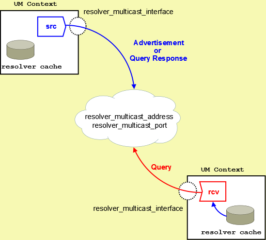
By default, Ultra Messaging relies on UDP-based Topic Resolution. UDP-based TR uses queries (TQRs) and advertisements (TIRs) to resolve topics. These TQRs and TIRs are sent in UDP datagrams, typically with more than one TIR or TQR in a given datagram.
UDP-based topic resolution traffic can benefit from hardware acceleration. See Transport Acceleration Options for more information.
For Multicast UDP, TR datagrams are sent to an IP multicast group and UDP port configured with the Ultra Messaging configuration options resolver_multicast_address (context) and resolver_multicast_port (context)).
For Unicast UDP, TR datagrams are sent to the IP address and port of the "lbmrd" daemon. See the UM configuration option resolver_unicast_daemon (context).
Note that if both Multicast and Unicast are configured, the Unicast has higher precedence, and Multicast will not be used.
UDP-based Topic Resolution occurs in the following phases:
- Initial Phase - Period that allows you to resolve a topic aggressively. This phase can be configured to run differently from the defaults or completely disabled.
- Sustaining Phase - Period that allows new receivers to resolve a topic after the Initial Phase. Can also be the primary period of topic resolution if you disable the Initial Phase. This phase can also be configured to run differently from the defaults or completely disabled.
- Quiescent Phase - The quiet phase where Topic Resolution datagrams are no longer sent in an unsolicited way. This reduces the CPU and network resources consumed by TR, and also reduces latency outliers (jitter). However, in large deployments, especially those that include wide-area networks, the Quiescent Phase is sometimes disabled, by configuring the Sustaining Phase to continue forever. This is done to avoid deafness issues.
The phases of topic resolution are specific to individual topics. A single context can have some topics in each of the three phases running concurrently.
Sources Advertise <-
For UDP-based TR, Sources use Topic Resolution in the following ways:
-
Unsolicited advertisement of active sources. When a source is first created, it enters the Initial Phase of TR. During the Initial, and subsequent Sustaining phases, the source sends Topic Information Record datagrams (TIRs) to all the other contexts in the TRD. The source does this in an unsolicited manner; it advertises even if there are no receivers for its topic.
- Respond to Topic Queries. When a receiver is first created, it enters the Initial phase of TR. During the Initial, and subsequent Sustaining phases, the receiver sends Topic Query Records (TQRs) to all other contexts in the TRD. When a source receives a TQR for its topic, it will restart its Sustaining Phase of advertising to ensure that the receiver discovers the source.
A TIR contains all the information that the receiver needs to join the topic's Transport Session. The TIR datagram sent unsolicited is identical to the TIR sent in response to a TQR. Depending on the transport type, a TIR will contain one of the following groups of information:
- For transporttcp, the source address, TCP port and Session ID.
- For Transport LBT-RM, the source address, the multicast group address, the UDP destination port, LBT-RM Session ID, and the unicast UDP port to which NAKs are sent.
- For Transport LBT-RU, the source address, UDP port and Session ID.
- For Transport LBT-IPC, the Host ID, LBT-IPC Session ID and Transport ID.
- For transportlbtsmx, the Host ID, LBT-SMX Session ID and Transport ID.
See UDP-Based Resolver Operation Options for more information.
Receivers Query <-
For UDP-based TR, when an application creates a receiver within a context, the new receiver first checks the context's resolver cache for any matching sources that the context has already discovered. Those will be joined immediately.
In addition, the receiver normally initiates a process of sending Topic Query Records (TQRs). This triggers sources for the receiver's topic to advertise, if they are not already. This allows sources which are in their Quiescent Phase to be discovered by new receivers.
A TQR consists primarily of the topic string.
Wildcard Receiver Topic Resolution <-
For UDP-based TR, UM Wildcard Receivers use Topic Resolution in conceptually the same ways as a single-topic receiver, although some of the details are different. Instead of searching the resolver cache for a specific topic, a new wildcard receiver object searches for all sources that match the wildcard pattern.
Also, the TQRs contain the wildcard pattern, and all sources matching the pattern will advertise.
Finally, wildcard receivers omit the Sustaining Phase for sending Queries. They only support Initial and Quiescent Phases.
See Wildcard Receiver Options for more information.
Initial Phase <-
For UDP-based TR, the initial topic resolution phase for a topic is an aggressive phase that can be used to resolve all topics before sending any messages. During the initial phase, network traffic and CPU utilization might actually be higher. You can completely disable this phase, if desired. See Disabling Aspects of Topic Resolution for more information.
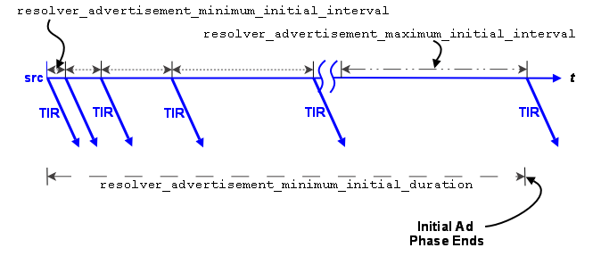
Advertising in the Initial Phase
For the initial phase default settings, the resolver issues the first advertisement as soon as the scheduler can process it. The resolver issues the second advertisement 10 ms later, or at the resolver_advertisement_minimum_initial_interval (source). For each subsequent advertisement, UM doubles the interval between advertisements. The source sends an advertisement at 20 ms, 40 ms, 80 ms, 160 ms, 320 ms and finally at 500 ms, or the resolver_advertisement_maximum_initial_interval (source). These 8 advertisements require a total of 1130 ms. The interval between advertisements remains at the maximum 500 ms, resulting in 7 more advertisements before the total duration of the initial phase reaches 5000 ms, or the resolver_advertisement_minimum_initial_duration (source). This concludes the initial advertisement phase for the topic.
The initial phase for a topic can take longer than the resolver_advertisement_minimum_initial_duration (source) if many topics are in resolution at the same time. The configuration options, resolver_initial_advertisements_per_second (context) and resolver_initial_advertisement_bps (context) enforce a rate limit on topic advertisements for the entire UM context. A large number of topics in resolution - in any phase - or long topic names may exceed these limits.
If a source advertising in the initial phase receives a topic query, it responds with a topic advertisement. UM recalculates the next advertisement interval from that point forward as if the advertisement was sent at the nearest interval.
Querying in the Initial Phase
Querying activity by receivers in the initial phase operates in similar fashion to advertising activity, although with different interval defaults. The resolver_query_minimum_initial_interval (receiver) default is 20 ms. Subsequent intervals double in length until the interval reaches 200 ms, or the resolver_query_maximum_initial_interval (receiver). The query interval remains at 200 ms until the initial querying phase reaches 5000 ms, or the resolver_query_minimum_initial_duration (receiver).
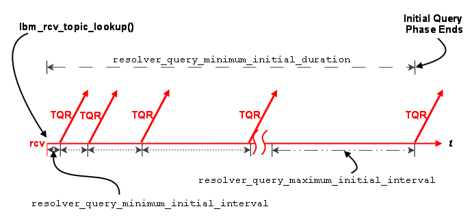
The initial query phase completes when it reaches the resolver_query_minimum_initial_duration (receiver). The initial query phase also has UM context-wide rate limit controls (resolver_initial_queries_per_second (context) and resolver_initial_query_bps (context)) that can result in the extension of a phase's duration in the case of a large number of topics or long topic names.
Sustaining Phase <-
For UDP-based TR, the sustaining topic resolution phase follows the initial phase and can be a less active phase in which a new receiver resolves its topic. It can also act as the sole topic resolution phase if you disable the initial phase. The sustaining phase defaults use less network resources than the initial phase and can also be modified or disabled completely. See Disabling Aspects of Topic Resolution for details.
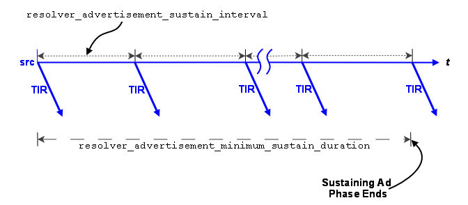
Advertising in the Sustaining Phase
For the sustaining phase defaults, a source sends an advertisement every second (resolver_advertisement_sustain_interval (source)) for 1 minute (resolver_advertisement_minimum_sustain_duration (source)). When this duration expires, the sustaining phase of advertisement for a topic ends. If a source receives a topic query, the sustaining phase resumes for the topic and the source completes another duration of advertisements.
The sustaining advertisement phase has UM context-wide rate limit controls (resolver_sustain_advertisements_per_second (context) and resolver_sustain_advertisement_bps (context)) that can result in the extension of a phase's duration in the case of a large number of topics or long topic names.
Querying in the Sustaining Phase
Default sustaining phase querying operates the same as advertising. Unresolved receivers query every second (resolver_query_sustain_interval (receiver)) for 1 minute (resolver_query_minimum_sustain_duration (receiver)). When this duration expires, the sustaining phase of querying for a topic ends.
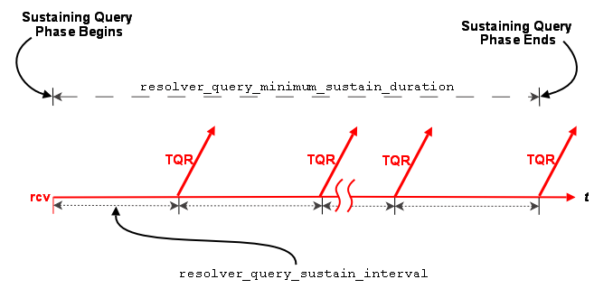
Sustaining phase queries stop when one of the following events occurs:
- The receiver discovers multiple sources that equal resolution_number_of_sources_query_threshold (receiver).
- The sustaining query phase reaches the resolver_query_minimum_sustain_duration (receiver).
The sustaining query phase also has UM context-wide rate limit controls (resolver_sustain_queries_per_second (context) and resolver_sustain_query_bps (context)) that can result in the extension of a phase's duration in the case of a large number of topics or long topic names.
Quiescent Phase <-
For UDP-based TR, this phase is the absence of topic resolution activity for a given topic. It is possible that some topics may be in the quiescent phase at the same time other topics are in initial or sustaining phases of topic resolution.
This phase ends if either of the following occurs.
- A new receiver sends a query.
- Your application calls lbm_context_topic_resolution_request() that provokes the sending of topic queries for any receiver or wildcard receiver in this state.
Store (context) Name Resolution <-
For UDP-based TR, with the UMP/UMQ products, topic resolution facilitates the resolution of persistent Store names to a DomainID:IPAddress:Port.
Topic Resolution resolves Store (or context) names by sending context name queries and context name advertisements over the topic resolution channel. A Store name resolves to the Store's DomainID:IPAddress:Port. You configure the Store's name and IPAddress:Port in the Store's XML configuration file. See Identifying Persistent Stores for more information.
If you do not use the DRO, the DomainID is zero. Otherwise, the DomainID represents the Topic Resolution Domain where the Store resides. Stores learn their DomainID by listening to Topic Resolution traffic.
Via the Topic Resolution channel, sources query for Store names and Stores respond with an advertisement when they see a query for their own Store name. The advertisement contains the Store's DomainID:IPAddress:Port.
For a new source configured to use Store names (ume_store_name (source)), the resolver issues the first context name query as soon as the scheduler can process it. The resolver issues the second advertisement 100 ms later, or at the resolver_context_name_query_minimum_interval (context). For each subsequent query, UM doubles the interval between queries. The source sends a query at 200 ms, 400 ms, 800 ms and finally at 1000 ms, or the resolver_context_name_query_maximum_interval (context). The interval between queries remains at the maximum 1000 ms until the total time querying for a Store (context) name equals resolver_context_name_query_duration (context). The default for this duration is 0 (zero) which means the resolver continues to send queries until the name resolves. After a Store name resolves, the resolver stops sending queries.
If a source sees advertisements from multiple Stores with the same name, or a Store sees an advertisement that matches its own Store name, the source issues a warning log message. The source also issues an informational log message whenever it detects that a resolved Store (context) name changes to a different DomainID:IPAddress:Port.
UDP Topic Resolution Configuration Options <-
See the following sections in UM Configuration Guide for more information:
- UDP-Based Resolver Operation Options
- Multicast Resolver Network Options
- Unicast Resolver Network Options
- Wildcard Receiver Options
Assigning Different Configuration Options to Individual Topics
You can set configuration options differently for individual topics, either by using XML Configuration Files (the <topic> element), or by using the API functions for setting configuration options programmatically (e.g. lbm_rcv_topic_attr_setopt() and lbm_src_topic_attr_setopt()).
Unicast UDP Topic Resolution <-
By default UM expects multicast connectivity between all sources and receivers. When only unicast connectivity is available, you may configure all sources and receivers to use unicast topic resolution. This requires that you run one or more instances of the UM unicast topic resolution daemon (lbmrd), which perform the same topic resolution activities as multicast topic resolution. You configure your applications to use the lbmrd daemons with resolver_unicast_daemon (context).
See Lbmrd Man Page for details on running the lbmrd daemon.
The lbmrd can run on any machine, including the source or receiver. Of course, sources will also have to select a transport protocol that uses unicast addressing (e.g. TCP, TCP-LB, or LBT-RU). The lbmrd maintains a table of clients (address and port pairs) from which it has received a topic resolution message, which can be any of the following:
- Topic Information Records (TIR) - also known as topic advertisements
- Topic Query Records (TQR)
- keepalive messages, which are only used in unicast topic resolution
After lbmrd receives a TQR or TIR, it forwards it to all known clients. If a client (source or receiver) is not sending either TIRs or TQRs, it sends a keepalive message to lbmrd according to the resolver_unicast_keepalive_interval (context). This registration with the lbmrd allows the client to receive advertisements or queries from lbmrd. lbmrd maintains no state about topics, only about clients.
LBMRD with the DRO Best Practice
If you're using the lbmrd for topic resolution across a DRO, you may want all of your domains discovered and all routes to be known before creating any topics. If so, change the UM configuration option, resolver_unicast_force_alive (context), from the default setting to 1 so your contexts start sending keepalives to lbmrd immediately. This makes your startup process cleaner by allowing your contexts to discover the other Topic Resolution Domains and establish the best routes. The trade-off is a little more network traffic every 5 seconds.
Unicast Topic Resolution Resilience
Running multiple instances of lbmrd allows your applications to continue operation in the face of a lbmrd failure. Your applications' sources and receivers send topic resolution messages as usual, however, rather than sending every message to each lbmrd instance, UM directs messages to lbmrd instances in a round-robin fashion. Since the lbmrd does not maintain any resolver state, as long as one lbmrd instance is running, UM continues to forward LBMR packets to all connected clients. UM switches to the next active lbmrd instance every 250-750 ms.
LBMRD NAT Transit <-
Some networks make use of a glossarynat NAT router to map one IP address space onto another. If your network architecture includes LANs that are bridged with a NAT device, UM receivers will usually not be able to connect directly to UM sources across the NAT. Sources send Topic Resolution advertisements containing their local IP addresses and ports, but receivers on the other side of the NAT cannot access those sources using those local addresses/ports. They must use alternate addresses/ports, which the NAT forwards according to the NAT's configuration.
The recommended method of establishing UM connectivity across a NAT is to run a pair of DROs connected with a single TCP peer link. In this usage, the LANs on each side of the NAT are distinct Topic Resolution Domains.
Alternatively, if the NAT can be configured to allow two-way UDP traffic between the networks, the lbmrd can be configured to modify Topic Resolution advertisements according to a set of rules defined in an XML configuration file. Those rules allow a source's advertisements forwarded to local receivers to be sent as-is, while advertisements forwarded to remote receivers are modified with the IP addresses and ports that the NAT expects. In this usage, the LANs on each side of the NAT are combined into a single Topic Resolution domain.
This is a lower-latency solution than dual DROs, but has significant restrictions.
Example NAT Configuration <-
In this example, there are two networks, A and B, that are interconnected via a NAT firewall. Network A has IP addresses in the 10.1.0.0/16 range, and B has IP addresses in the 192.168.1/24 range. The NAT is configured such that hosts in network B have no visibility into network A, and can send TCP and UDP packets to only a single host in A (10.1.1.50) via the NAT's external IP address 192.168.1.1, ports 12000 and 12001. Packets sent from B to 192.168.1.1:12000 are forwarded to 10.1.1.50:12000, and packets from B to 192.168.1.1:12001 are forwarded to 10.1.1.50:12001. Hosts in network A have full visibility of network B and can send TCP and UDP packets to hosts in B by their local 192 addresses and ports. Those packets have their source addresses changed to 192.168.1.1.
Since hosts in network A have full visibility into network B, receivers in network A should be able to use source advertisements from network B without any changes. However, receivers in network B will not be able to use source advertisements from network A unless those advertisements' IP addresses are transformed.
The lbmrd is configured for NAT using its XML configuration file:
The lbmrd must be run on 10.1.1.50.
The application on 10.1.1.50 should be configured with:
context resolver_unicast_daemon 10.1.1.50:12000
source transport_tcp_port 12001
The applications in the 192 network should be configured with:
context resolver_unicast_daemon 192.168.1.1:12000
source transport_tcp_port 12100
With this, the application on 10.1.1.50 is able to create sources and receivers that communicate with applications in the 192 network.
See lbmrd Configuration File for full details of the XML configuration file.
Lbmrd NAT Restrictions <-
- TCP-based Topic Resolution using the SRS does not support this form of NAT operation. If you want to mix SRS and lbmrd operation on the same network, contact UM Support.
- Persistence - not supported.
- Queuing - not supported.
- Request/Response - not supported.
- Unicast Immediate Messaging (UIM) - not supported.
- Late Join - limited supported.
- Off-Transport Recovery (OTR) - limited supported.
- Sending to Sources - limited supported.
Late Join, sending to sources, and OTR can be made to work if applications are configured to use the default value (0.0.0.0) for request_tcp_interface (context). This means that you cannot use default_interface (context). Be aware that the DRO requires a valid interface be specified for request_tcp_interface (context). Thus, lbmrd NAT support for Late Join, Request/Response, and OTR is not compatible with UM topologies that contain the DRO.
UDP-Based Topic Resolution Strategies <-
Configuring UDP-based TR frequently involves a process of weighing the costs and benefits of different goals. The most common goals involved are:
- Avoid "deafness". deafness is when there is a source and a receiver for a topic, but the receiver does not discover the source. This is usually a very high priority goal.
- Minimize the delay before a transport session is joined. This is especially important when a new source is created and the application wants to wait until all existing receivers have fully joined the transport session before sending messages.
- Minimizing impact on the system. Sending and receiving TR datagrams consumes CPU, network bandwidth, and can introduce latency outliers (jitter) on active data transports.
- Maximizing scalability and flexibility. Some deployments are tightly-coupled, carefully controlled, and well-defined. In those cases, scalability and flexibility might not be high-priority goals. Other deployments are loosely-coupled, and consist of many different application groups that do not necessarily coordinate their use of UM with each other. In those cases, scalability and flexibility can be important.
- Fault tolerance. Some environments, especially those that include Wide Area Networks, can have periodic degradation or loss of network connectivity. It is desired that after a given network problem is resolved, UM will quickly and automatically reestablish normal operation without deafness.
The right TR strategy for a given deployment can depend heavily on the relative importance of these and other goals. It is impossible to give a "one size fits all" solution. Most users work with Informatica engineers to design a custom configuration.
Most users employ a variation on a few basic strategies. Note for the most part, these strategies do not depend on the specific UDP protocol (Multicast vs. Unicast). Normally Multicast is chosen, except where network or policy restrictions forbid it.
Default TR <-
The main characteristics of UM's default TR settings are:
- Multicast UDP.
- Three phases enabled (Initial, Sustaining, Quiescent). Unsolicited TIRs and TQRs nominally last for 65 seconds, although that number can grow as the number of sources or receivers in a context increases.
The default settings can be fine for reasonably small, static deployments, typically not including Wide Area Networks. (A "static" deployment is one where sources, and receivers are, for the most part, created during system startup, and deleted during system shutdown. Contrast with a "dynamic" system where applications come and go during normal operation, with sources and receivers being created and deleted at unpredictable times.)
Advantages:
- Simplicity.
- In a network where sources and receivers are relatively static, the consumption of resources by TR stops reasonably quickly.
Disadvantages:
- As the numbers of contexts, sources, and receivers grow, the traffic load during the initial phase can be very intense, leading to packet loss and potential deafness issues. In these cases, the initial phase can be configured to be less aggressive, or disabled altogether.
- If a network outage lasts longer than 65 seconds, it is possible for new sources and receivers to be deaf to each other, due to entering their quiescent phases. In these cases, the sustaining phase can be configured for longer durations.
Query-Centric TR <-
The main characteristics of Query-centric TR are:
- Unsolicited TIRs are severely limited or disabled. See Disabling Aspects of Topic Resolution.
- TQRs are extended, often to infinity.
Query-centric TR can be useful for large-scale, dynamic systems, especially those that may have many sources for which there are no receivers during normal operation. For example, in some market data distribution architectures, many tens of thousands of sources are created, but a fairly small percentage of them have receivers at any given time. In that case, it is unnecessary to advertise sources on topics that have no receivers.
Note that this strategy does not prevent advertisements. Each TQR will trigger one or more sources to send a TIR in response.
Advantages:
- For some deployments, can result in significantly reduced TR loading due to removal of TIRs for topics with no receivers.
Disadvantages:
- To avoid deafness issues, the Query sustaining phase is usually extended, often to infinity. This consumes CPU and Network bandwidth, and can introduce latency outliers (jitter).
- For topics that have receivers, both TQR and TIR traffic are present. (In contrast, a Advertise-Centric TR strategy removes the TQRs, but at the expense of advertising all sources, even those that have no receivers.)
Known Query Threshold TR <-
In a special case of Query-centric TR, certain classes of topics have a specific number of sources. For example, in point-to-point use cases, a particular topic has exactly one source. As another example, some market data distribution architectures have two sources for each topic, a primary and a warm standby.
For those topics where it is known how many sources there should be, the configuration option resolution_number_of_sources_query_threshold (receiver) can be combined with Query-centric TR to great benefit. Configure the receiver to query forever, and configure the query threshold to the number of expected sources. When the receiver discovers at least that many sources for the topic, it suppresses queries. Note that if a source exits and the receiver detects EOS, the number of known sources decreases. If the number drops below the threshold, queries resume.
For example, consider a market data system with a primary and warm standby source for each topic. Unsolicited advertisements are disabled (see Disabling Aspects of Topic Resolution), and resolution_number_of_sources_query_threshold (receiver) is set to 2. The receiver will query until it has discovered two sources, at which point it will stop sending queries. If a source fails, the receiver resumes sending queries until it again has two sources.
The advantage here is that it is no longer necessary to extend the Sustaining phase forever to avoid deafness.
NOTE: wildcard receivers do not fit well with this model of TR. Wildcard receivers have their own query mechanism; see Wildcard Receiver Topic Resolution. In particular, there is no wildcard equivalent to the number of sources query threshold. In a query-centric model, wildcard queries must be extended to avoid potential deafness issues. However, in most deployments, the number of wildcard receiver objects is small compared to the number of regular single-topic receivers, so using the Known Query Threshold TR model can still be beneficial.
Advertise-Centric TR <-
The main characteristics of Advertise-centric TR are:
- Unsolicited TQRs are severely limited or disabled. See Disabling Aspects of Topic Resolution.
- TIRs are extended, often to infinity.
Advertise-centric TR can be useful for large-scale, dynamic systems, especially those that may have very few sources for which there are no receivers. For example, most order management and routing systems use messaging in a point-to-point fashion, and every source should have a receiver. In that case, it is unnecessary to extend queries.
Advantages:
- For some deployments, can result in moderate reduced TR loading due to reduction of TQRs.
Disadvantages:
- To avoid deafness issues, the Advertising sustaining phase is usually extended, often to infinity. This consumes CPU and Network bandwidth, and can introduce latency outliers (jitter).
- For topics that have no receivers, TIR traffic is present. (In contrast, a Query-Centric TR strategy removes the TIRs for topics that have no receivers, but at the expense of introducing both TQRs and TIRs.)
- In a deployment that includes the DRO, some number of TQRs are necessary to inform the Router that the context is interested in the topic. To avoid deafness issues, it is recommended to extend the Querying Sustaining Phase, although at a reduced rate.
- If the resolution_no_source_notification_threshold (receiver) feature is used, some number of TQRs are necessary.
Message Batching <-
This section is about source-side batching - publishers batching messages when sending. See also Receive-Side Batching.
Batching many small messages into fewer network packets decreases the per-message CPU load, thereby increasing throughput. Let's say it costs 2 microseconds of CPU to fully process a message. If you process 10 messages per second, you won't notice the load. If you process half a million messages per second, you saturate the CPU. So to achieve high message rates, you have to reduce the per-message CPU cost with some form of message batching. These per-message costs apply to both the sender and the receiver.
Many people are under the impression that while batching reduces CPU load, it increases message latency. There are circumstances where this can happen, but it is also true that careful use of batching can result in small latency increases or none at all. In fact, there are common circumstances where Intelligent Batching will reduce average latency.
The most common forms of source-side batching employed with UM are:
Note that implicit and intelligent batching are not supported for UMQ Brokered Queuing, Smart Sources, or Transport LBT-SMX.
When using a kernel-bypass network driver (e.g. Solarflare's Onload), there are special considerations when batching. See Datagram Max Size and Network MTU.
Implicit Batching <-
With implicit batching, UM automatically batches smaller messages into Transport Session datagrams. The implicit batching configuration options, implicit_batching_interval (source) (default = 200 milliseconds) and implicit_batching_minimum_length (source) (default = 2048 bytes) govern UM implicit message batching. Although these are source options, they actually apply to the Transport Session to which the source was assigned.
See Implicit Batching Options.
See also Source Configuration and Transport Sessions.
UM establishes the implicit batching parameters when it creates the Transport Session. Any sources assigned to that Transport Session use the implicit batching limits set for that Transport Session, and the limits apply to any and all sources subsequently assigned to that Transport Session. This means that batched transport datagrams can contain messages on multiple topics.
Implicit Batching Operation
Implicit Batching buffers messages until:
- the buffer size exceeds the configured implicit_batching_minimum_length (source), or
- the oldest message in the buffer has been in the buffer for implicit_batching_interval (source) milliseconds, or
- adding another message would cause the buffer to exceed the configured Datagram Max Sizes for the underlying transport type.
When at least one condition is met, UM flushes the buffer, pushing the messages onto the network.
Note that the two size-related parameters operate somewhat differently. When the application sends a message, the implicit_batching_minimum_length (source) option will trigger a flush after the message is sent. A sent datagram will typically be larger than the value specified by implicit_batching_minimum_length (source) (hence the use of the word "minimum"). In contrast, the transport_*_datagram_max_size option will trigger a flush before the message is sent. A sent datagram will never be larger than the transport_*_datagram_max_size option. If both size conditions apply, the Datagram Max Sizes takes priority.
It may appear this design introduces significant latencies for low-rate topics. However, remember that Implicit Batching operates on a Transport Session basis. Typically many low-rate topics map to the same Transport Session, providing a high aggregate rate. The implicit_batching_interval (source) option is a last resort to prevent messages from becoming stuck in the Implicit Batching buffer. If your UM deployment frequently uses the implicit_batching_interval (source) to push out the data (if the entire Transport Session has periods of inactivity longer than the value of implicit_batching_interval (source) (defaults to 200 ms), then either the implicit batching options need to be fine-tuned (reducing one or both), or you should consider an alternate form of batching. See Intelligent Batching.
The minimum value for the implicit_batching_interval (source) is 3 milliseconds. The actual minimum amount of time that data stays in the buffer depends on your Operating System and its scheduling clock interval. For example, on a Solaris 8 machine, the actual time is can be as much as 20 milliseconds. On older Microsoft Windows machines, the time can be as much as 16 milliseconds. On a Linux 2.6 kernel, the actual time is 3 milliseconds (+/- 1).
Implicit Batching Example
The following example demonstrates how the implicit_batching_minimum_length (source) is actually a trigger or floor, for sending batched messages. It is sometimes misconstrued as a ceiling or upper limit.
source implicit_batching_minimum_length 2000
- The first send by your application puts 1900 bytes into the batching buffer, which is below the minimum, so UM holds it.
- The second send fills the batching buffer to 3800 bytes, well over the minimum. UM sends it down to the transport layer, which builds a 3800-byte (plus overhead) datagram and sends it.
- The sender's Operating System performs IP fragmentation on the datagram to produce packets, and the receiving Operating System reassembles the datagram.
- UM reads the datagram from the socket at the receiver.
- UM parses out the two messages and delivers them to the appropriate topic levels, which deliver the data.
The proper setting of the implicit batching parameters often represents a trade-off between latency and efficiency, where efficiency affects the highest throughput attainable. In general, a large minimum length setting increases efficiency and allows a higher peak message rate, but at low message rates a large minimum length can increase latency. A small minimum length can lower latency at low message rates, but does not allow the message rate to reach the same peak levels due to inefficiency. An intelligent use of implicit batching and application-level flushing can be used to implement an adaptive form of batching known as Intelligent Batching which can provide low latency and high throughput with a single setting.
Implicit Batching Restrictions
- The Smart Sources feature does not support implicit batching.
- The Unicast Immediate Messaging and Multicast Immediate Messaging APIs don't support implicit batching.
- The response APIs associated with the Request/Response Model do not support implicit batching.
Intelligent Batching <-
Intelligent Batching uses Implicit Batching along with your application's knowledge of the messages it must send. It is a form of dynamic adaptive batching that automatically adjusts for different message rates. Intelligent Batching can provide significant savings of CPU resources without adding any noticeable latency.
For example, your application might receive input events in a batch, and therefore know that it must produce a corresponding batch of output messages. Or the message producer works off of an input queue, and it can detect messages in the queue. In any case, if the application knows that it has more messages to send without going to sleep, it simply does normal sends to UM, letting Implicit Batching send only when the buffer meets the implicit_batching_minimum_length (source) threshold.
However, when the application detects that it has no more messages to send after it sends the current message, it sets the FLUSH flag (LBM_MSG_FLUSH) when sending the message which instructs UM to flush the implicit batching buffer immediately by sending all messages to the transport layer. Refer to lbm_src_send() in the UM API documentation (UM C API, UM Java API, or UM .NET API) for all the available send flags.
When using Intelligent Batching, it is usually advisable to increase the implicit_batching_minimum_length (source) option to 10 times the size of the average message, to a maximum value of 8196. This tends to strike a good balance between batching length and flushing frequency, giving you low latencies across a wide variation of message rates.
Application Batching <-
In all of the above situations, your application sends individual messages to UM and lets UM decide when to push the data onto the wire (often with application help). With application batching, your application buffers messages itself and sends a group of messages to UM with a single send. Thus, UM treats the send as a single message. On the receiving side, your application needs to know how to dissect the UM message into individual application messages.
This approach is most useful for Java or .NET applications where there is a higher per-message cost in delivering an UM message to the application. It can also be helpful when using an event queue to deliver received messages. This imposes a thread switch cost for each UM message. At low message rates, this extra overhead is not noticeable. However, at high message rates, application batching can significantly reduce CPU overhead.
Explicit Batching <-
- Warning
- The Explicit Batching feature is deprecated and may be removed in a future release. Users are advised to use Implicit Batching or Intelligent Batching.
UM allows you to group messages for a particular topic with explicit batching. The purpose of grouping messages with explicit batching is to allow the receiving application to detect the first and last messages of a group without needing to examine the message contents.
- Note
- Explicit Batching does not guarantee that all the messages of a group will be sent in a single datagram.
- Warning
- Explicit Batching does not provide any kind of transactional guarantee. It is possible to receive some messages of a group while others are unrecoverably lost. If the first and/or last messages of a group are unrecoverably lost, then the receiving application will not have an indication of start and/or end of the group.
When your application sends a message (lbm_src_send()) it may flag the message as being the start of a batch (LBM_MSG_START_BATCH) or the end of a batch (LBM_MSG_END_BATCH). All messages sent between the start and end are grouped together. The flag used to indicate the end of a batch also signals UM to send the message immediately to the implicit batching buffer. At this point, Implicit Batching completes the batching operation. UM includes the start and end flags in the message so receivers can process the batched messages effectively.
Unlike Intelligent Batching which allows intermediate messages to trigger flushing according to the implicit_batching_minimum_length (source) option, explicit batching holds all messages until the batch is completed. This feature is useful if you configure a relatively small implicit_batching_minimum_length (source) and your application has a batch of messages to send that exceeds the implicit_batching_minimum_length (source). By releasing all the messages at once, Implicit Batching maximizes the size of the network datagrams.
Explicit Batching Example
The following example demonstrates explicit batching.
source implicit_batching_minimum_length 8000
- Your application performs 10 sends of 100 bytes each as a single explicit batch.
- At the 10th send (which completes the batch), UM delivers the 1000 bytes of messages to the implicit batch buffer.
- Let's assume that the buffer already has 7899 bytes of data in it from other topics on the same Transport Session
- UM adds the first 100-byte message to the buffer, bringing it to 7999.
- UM adds the second 100-byte message, bringing it up to 8099 bytes, which exceeds implicit_batching_minimum_length (source) but is below the 8192 Datagram Max Sizes.
- UM sends the 8099 bytes (plus overhead) datagram.
- UM adds the third through tenth messages to the implicit batch buffer. These messages will be sent when either implicit_batching_minimum_length (source) is again exceeded, or the implicit_batching_interval (source) is met, or a message arrives in the buffer with the flush flag (LBM_MSG_FLUSH) set.
Adaptive Batching <-
- Warning
- The Adaptive Batching feature is deprecated and may be removed in a future release. Users are advised to use Implicit Batching or Intelligent Batching.
Message Fragmentation and Reassembly <-
Message fragmentation is the process by which an arbitrarily large message is split into a series of smaller pieces or fragments. Reassembly is the process of putting the pieces back together into a single contiguous message. Ultra Messaging performs UM fragmentation and reassembly on large user messages. When a user message is small enough, it fits into a single fragment.
Note that there is another layer of fragmentation and reassembly that happens in the TCP/IP network stack, usually by the host operating system. This IP fragmentation of datagrams into packets happens when sending datagrams larger than the MTU of the network medium, usually 1500 bytes. However, this fragmentation and reassembly happens transparently to and independently of Ultra Messaging. In the UM documentation, "fragmentation" generally refers to the higher-level UM fragmentation.
Some users of UM have configured their network and systems for "jumbo frames", which provides an MTU of up to 9000 bytes. This can provide efficiency benefits, but is not practical for most users. This document assumes an MTU of 1500.
Another term that Ultra Messaging borrows from networking is "datagram". In the UM documentation, a datagram is a unit of data which is sent to the transport (network socket or shared memory). In the case of network-based transport types, this refers to a buffer which is sent to the network socket in a single system call.
(Be aware that for UDP-based transport types (LBT-RM and LBT-RU), the UM datagrams are in fact sent as UDP datagrams. For non-UDP-based transports, the use of the term "datagram" is retained for consistency.)
The mapping of message fragments to datagrams depends on three factors:
- User message size,
- Configured Datagram Max Sizes for the source's transport type, and
- Use of the Implicit Batching feature.
When configured, the source implicit batching feature combines multiple small user messages into a single datagram no greater than the size of the transport type's configured Datagram Max Sizes.
Large user messages can be split into N fragments, the first N-1 of which are approximately the size of the transport type's configured Datagram Max Sizes, and the Nth fragment containing the left-over bytes.
A subscriber's receiver callback can get information about a message's fragments by calling lbm_msg_retrieve_fragment_info().
A publisher can test an individual sent message to see if UM fragmented it via the LBM_SRC_EVENT_SEQUENCE_NUMBER_INFO source event, which is enabled by sending the message using the lbm_src_send_ex() function and setting the LBM_SRC_SEND_EX_FLAG_SEQUENCE_NUMBER_INFO flag or LBM_SRC_SEND_EX_FLAG_SEQUENCE_NUMBER_INFO_FRAGONLY flag.
- Note
- The SMX transport type does not support fragmentation.
Datagram Max Sizes <-
Each transport type has its own default maximum datagram size. For example, LBT-RM and LBT-RU have 8K as their default maximum datagram sizes, while TCP and IPC have 64K as their default maximums. These different defaults represent optimal values for the different transport types, and in a simple UM network, it is usually not necessary to change them.
The configuration options are:
- transport_tcp_datagram_max_size (context)
- transport_lbtrm_datagram_max_size (context)
- transport_lbtru_datagram_max_size (context)
- transport_lbtipc_datagram_max_size (context)
- transport_lbtsmx_datagram_max_size (source) - note this is a source-scoped option; the others are context-scoped.
Note that the transport's datagram max size option limits the size of the UM payload, and does not include overhead specific to the underlying transport type. For example, transport_lbtrm_datagram_max_size (context) does not include the UDP, IP, or packet overhead. The actual network frame can be larger than than the configured datagram max size.
- Attention
- When a DRO is being used in a UM network, it is usually advisable to override the different transports' datagram max sizes to make them all the same. This should be done for all applications and UM daemons, in all Topic Resolution Domains (TRDs). See DRO Protocol Conversion.
Datagram Max Size and Network MTU <-
By default, when a UM source is building an outgoing message, it reserves space for the largest possible UM header. This fixed-size reservation is subtracted from the configured datagram max size to determine how much user data can be added to the datagram. Since most UM messages do not need a large UM header, there can be cases where a user message that could fit in a single datagram without exceeding the configured datagram limit will instead be split into two fragments, each carried in a datagram that is significantly below the configured datagram limit.
When UM is configured with a datagram max size of 8K or more, this space inefficiency does not pose a noticeable problem since the header reservation is a small percentage of the full 8K. However, for users who want to avoid IP fragmentation, the datagrams should be limited to 1472 bytes. In this case, the space inefficiency becomes objectionable; packets will often not be as full as they should be.
For most networks, Informatica recommends setting the Datagram Max Sizes to a minimum of 8K, and allowing the operating system to perform IP fragmentation. Some network engineers have learned that IP fragmentation can place a burden on network hardware (routers and switches), but this is true only if the network network hardware has to perform the fragmentation. For most modern networks, the entire fabric is designed to handle a common MTU, typically of 1500 bytes. Thus, a UDP datagram larger than 1500 bytes is fragmented once by the sending host's operating system, and the switches and routers only need to forward the already-fragmented packets. Switches and routers can forward fragmented packets without burden.
There are typically two circumstances where users should set UM's Datagram Max Sizes to a smaller value:
- If kernel bypass network drivers are being used which either don't handle IP fragments at all, or does handle them but only via the "slow path" (not accelerated).
- If the smallest MTU across a network path is smaller than the MTU of a host's network interface. For example, your hosts typically have an Ethernet connection with a 1500-byte MTU. But a WAN link might have a much smaller MTU. In that case, UM's Datagram Max Sizes should be set to a value that keeps all packets within the WAN link's MTU. Note that in modern networks, it is rare to find links with an MTU below 1500.
In both cases, the space inefficiency caused by reserving space for the largest possible UM header is objectionable.
The preferred solution is to use UM version 6.14 or beyond and enable the Dynamic Fragmentation Reduction feature.
For pre-6.14 UM, it can be possible to artificially increase the Datagram Max Sizes to a value above the desired limit. See Setting Datagram Max Sizes High.
- Note
- UM version 6.12 changed the amount of space that Smart Sources reserve for the UM header. This can mean that pre-6.12 smart source users upgrading to 6.12 or beyond may need to change their configuration. See Smart Source Header Size Change.
Setting Datagram Max Sizes High <-
There are cases when the Datagram Max Sizes must be set to a relatively small value to prevent IP fragmentation. However, as described in Datagram Max Size and Network MTU, this is space inefficient and can result in more UM fragmentation than is necessary.
Some users set their datagram max size to a value above the desired limit, knowing that LBT-RM and LBT-RU will reserve a large number of bytes for the largest possible UM header. This allows traffic to more-efficiently fill packets, and therefore avoid unnecessary UM fragmentation. However, this technique is imperfect.
Setting the datagram max size above the desired limit technically gives UM permission to send a datagram up to that size. You cannot always count on the largest possible header space being reserved. In practice with a restricted use case (e.g. flushing every message), LBT-RM data messages may never go above the desired limit. But TSNI messages can reach the full datagram max size, and so can implicitly batched messages.
Also, keep in mind that UM does not publish the internal reserved size, and does not guarantee that the reserved size will stay the same. Users who use this technique must determine their optimal datagram max size empirically through extensive testing within the constraints of their use cases.
Starting with UM version 6.14, Informatica recommends that kernel bypass users make use of the Dynamic Fragmentation Reduction feature. This allows setting the datagram max size to 1472 to prevent IP fragmentation, while ensuring that data messages are not unnecessarily fragmented.
Changing Datagram Max Size <-
For UM versions prior to 6.17, changing a UM network's datagram max size required changing all UM-based components (applications and UM daemons) at the same time. You couldn't gradually change some components to a different size while leaving other components are their original size. This is because if a component with a larger datagram max size sends a datagram larger than a subscriber's datagram max size, the subscriber's receive buffer will be insufficient to hold the datagram, resulting in unrecoverable loss. By changing all components at the same time, a sender will fragment large messages to the proper size for subscribers' receive buffers.
This "all at once" requirement for changing the datagram max size presents a challenge to larger organizations that desire to migrate towards kernel bypass technology (like Solarflare's Onload driver).
Starting with UM version 6.17, a component can be configured for different datagram max sizes for sending and receiving. See transport_lbtrm_receiver_datagram_max_size (context), transport_lbtrm_source_datagram_max_size (context), transport_lbtru_receiver_datagram_max_size (context), and transport_lbtru_source_datagram_max_size (context). Note that a receiver's datagram max size can be set larger than a source's; it is reliable to have a larger receive size, although it does use more memory.
So, for example, in the case of wanting to reduce the datagram max size to accommodate kernel bypass drivers, you would first reduce all publishers' "source" datagram max size to 1472 (Dynamic Fragmentation Reduction is recommended). This can be done gradually, small groups of publishers at a time, concentrating first on those publishers that need kernel bypass as a high priority.
Once all components have their source datagram max sizes reduced, then the receiver datagram max size can be reduced to the same value.
It is less common, though still supported, to increase the datagram max size using the opposite process: first increase the receivers datagram max size, then increase the source.
Many users choose not to accelerate UDP-based topic resolution, so it may not be necessary to change the TR datagram max size. But should it be necessary, the same principles apply: change the TR receiver's datagram size with resolver_receiver_datagram_max_size (context) and the sender's with resolver_source_datagram_max_size (context).
Dynamic Fragmentation Reduction <-
As described in Datagram Max Size and Network MTU, UM versions prior to 6.14 reserved an unnecessarily large size in each datagram for a worst-case header, resulting in the LBT-RM and LBT-RU protocols performing UM fragmentation at message sizes where they should not have to. In an effort to more-fully fill data packets, some users set their Datagram Max Sizes above an MTU, but this can result in IP fragmentation.
Starting with UM version 6.14, enabling dynamic_fragmentation_reduction (context) lets UM's transport protocols more-fully utilize the configured datagram max size, thus avoiding unnecessary UM and IP fragmentation. This option is typically only of interest to users of LBT-RM and/or LBT-RU who need to avoid IP fragmentation, such as users of a kernel-bypass driver.
This allows the user to set the desired transport's datagram max size option to 1472, which prevents IP fragmentation on the transport session, while still efficiently filling the packets to close to the MTU.
Enabling Dynamic Fragmentation Reduction
Users of kernel bypass drivers sometimes set their datagram max sizes well above 1472. This avoids inefficient filling of packets, but still carries the risk that some messages will trigger IP fragmentation.
To use the Dynamic Fragmentation Reduction feature:
context dynamic_fragmentation_reduction 1
context transport_lbtrm_datagram_max_size 1472
context transport_lbtru_datagram_max_size 1472
# Technically, only RM and RU matter. But when DROs are present, allow
# protocol conversion by making all transports the same.
context transport_tcp_datagram_max_size 1472
context transport_lbtipc_datagram_max_size 1472
source transport_lbtsmx_datagram_max_size 1472
DRO users see Protocol Conversion.
Upgrade Path
The Dynamic Fragmentation Reduction feature is designed to allow a gradual upgrade. Older versions of UM can interoperate with 6.14 and beyond using Dynamic Fragmentation Reduction, but certain requirements must be met.
Users interested in Dynamic Fragmentation Reduction are typically users of kernel-bypass drivers who want to set their datagram max sizes to 1 MTU. For efficiency purposes, they've empirically determined an optimal value which is noticeably higher than a network MTU. A typical value might be between 1800 and 1900.
During the upgrade period, you will be running upgraded UM programs (version 6.14 or beyond) with Dynamic Fragmentation Reduction enabled, and datagram max sizes set to 1472. These will successfully interoperate with older UM versions running with datagram max sizes between 1800 and 1900.
The exception to this rule is the DRO. In a mixed-version environment, the DRO should always be configured with the largest datagram max size values used in your network. If an older version application is set to 1800, a DRO running 6.14 or beyond should also be configured for 1800.
See also Protocol Conversion.
Ordered Delivery <-
With the Ordered Delivery feature, a receiver's Delivery Controller can deliver messages to your application in sequence number order or arrival order. This feature can also reassemble fragmented messages or leave reassembly to the application. You can set Ordered Delivery via UM configuration option to one of three modes:
- Sequence Number Order, Fragments Reassembled
- Arrival Order, Fragments Reassembled
- Arrival Order, Fragments Not Reassembled (deprecated)
See ordered_delivery (receiver)
Note that these ordering modes only apply to a specific topic from a single publisher. UM does not ensure ordering across different topics, or on a single topic across different publishers. See Message Ordering for more information.
Sequence Number Order, Fragments Reassembled (Default Mode) <-
In this mode, a receiver's Delivery Controller delivers messages in sequence number order (the same order in which they are sent). This feature also guarantees reassembly of fragmented large messages. To enable sequence number ordered delivery, set the ordered_delivery (receiver) configuration option as shown:
receiver ordered_delivery 1
Please note that ordered delivery can introduce latency when packets are lost (new messages are buffered waiting for retransmission of lost packets).
Arrival Order, Fragments Reassembled <-
This mode delivers messages immediately upon reception, in the order the datagrams are received, except for fragmented messages, which UM holds and reassembles before delivering to your application. Be aware that messages can be delivered out of order, either because of message loss and retransmission, or because the networking hardware re-orders UDP packets. Your application can then use the sequence_number field of lbm_msg_t objects to order or discard messages. But be aware that the sequence number may not always increase by 1; application messages larger than the Datagram Max Sizes will be split into fragments, and each fragment gets its own sequence number. With the "Arrival Order, Fragments Reassembled" mode of delivery, UM will reassemble the fragments into the original large application message and deliver it with a single call to the application receiver callback. But that message's sequence_number will reflect the final fragment.
To enable this arrival-order-with-reassembly mode, set the following configuration option as shown:
receiver ordered_delivery -1
Arrival Order, Fragments Not Reassembled <-
- Warning
- This mode of delivery is deprecated and may be removed in a future version. The user is advised to use mode -1.
This mode allows messages to be delivered to the application immediately upon reception, in the order the datagrams are received. If a message is lost, UM will retransmit the message. In the meantime, any subsequent messages received are delivered immediately to the application, followed by the dropped packet when its retransmission is received. This mode has the lowest latency.
With this mode, the receiver delivers messages larger than the transport's Datagram Max Sizes as individual fragments. The C API function, lbm_msg_retrieve_fragment_info() returns fragmentation information for the message you pass to it, and can be used to reassemble large messages. (In Java and .NET, LBMMessage provides methods to return the same fragment information.) Note that reassembly is not required for small messages.
To enable this no-reassemble arrival-order mode, set the following configuration option as shown:
receiver ordered_delivery 0
When developing message reassembly code, consider the following:
- Message fragments don't necessarily arrive in sequence number order.
- Some message fragments may never arrive (unrecoverable loss), so you must time out partial messages.
Arrival order delivery without reassembly is not compatible with the following UM features:
Loss Detection Using TSNIs <-
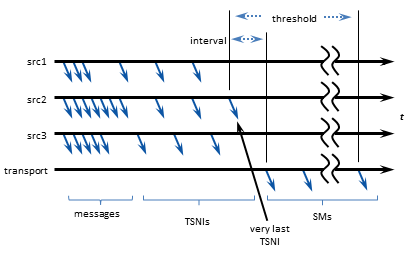
A TSNI (Topic Sequence Number Information) message is an internal UM message sent by a source to inform receivers of the topic-level sequence number of the last message sent.
When a source enters an idle period during which it has no data traffic to send (5 seconds by default), that source will send one or more TSNI messages. The TSNI lets receivers know that the source is still active and also reminds receivers of the sequence number of the last message. This helps receivers become aware of any lost messages prior to the TSNI.
Sources send TSNIs over the same transport and on the same topic as normal data messages. You can set a time value of the TSNI interval with configuration option transport_topic_sequence_number_info_interval (source). You can also set a time value for the duration that the source sends contiguous TSNIs with configuration option transport_topic_sequence_number_info_active_threshold (source), after which time the source stops issuing TSNIs.
Receiver Keepalive Using Session Messages <-
When an LBT-RM, LBT-RU, or LBT-IPC Transport Session enters an inactive period during which it has no messages to send, the UM context sends Session Messages (SMs). The first SM is sent after 200 milliseconds of inactivity (by default). If the period of inactivity continues additional SMs will be sent at increasing intervals, up to a maximum interval of 10 seconds (by default).
SMs serve three functions:
- Keepalive - SMs inform receivers that transport sessions are still alive. If a receiver stops getting any kind of traffic for a transport session, after a configurable period of inactivity the receiver will time out the transport session and will assume that it has died.
- Tail loss - for UDP-based transport sessions (LBT-RM and LBT-RU), SMs are used to detect packet loss, specifically "tail loss", and trigger recovery.
- Multicast Flows - for multicast-based transport sessions (LBT-RM), SMs serve to keep the network hardware multicast flows "hot", so that replication and forwarding of multicast packets is done in hardware at line speed.
Any other UM message on a transport session will suppress the sending of SMs, including data messages and TSNIs. (Topic Resolution messages are not sent on the transport session, and will not suppress sending SMs.) You can set time values for SM interval and duration with configuration options specific to their transport type.
Extended Messaging Example <-
This section illustrates many of the preceding concepts using an extended example of message passing. This example uses LBT-RM, but for the purposes of this example, LBT-RU operates in a similar manner.
The example starts out with two applications, Publisher and Subscriber:
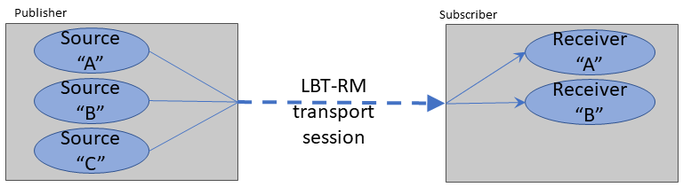
The publisher has created three source objects, for topics "A", "B", and "C" respectively. All three sources are mapped to a single LBT-RM Transport Session by configuring them for the same multicast group address and destination port.
The Subscriber application creates two receivers, for topics "A" and "B".
The creation of sources and receivers triggers Topic Resolution, and the subscriber joins the Transport Session once the topics are resolved. To be precise, the first receiver to discover a source triggers joining the Transport Session and creating a Delivery Controller; subsequent source discoveries on the same Transport Session don't need to join; they only create Delivery Controllers. However, until such time as one or more publishing sources send their first topic-layer message, the source Transport Session sends no datagrams. The Transport Session is created, but has not yet "started".
Example: First Message <-
In this example, the first message on the Transport Session is generated by the publishing application sending an application message, in this case for topic "A".
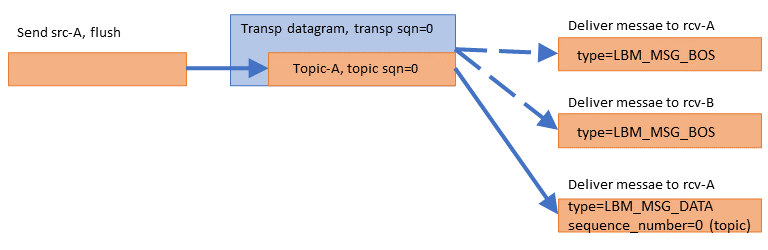
The send function is passed the "flush" flag so that the message is sent immediately. The message is assigned a topic-level sequence number of 0, since it is the application's first message for that topic. The source-side transport layer wraps the application message in a datagram and gives it transport sequence number 0, since it is the first datagram sent on the Transport Session.
On the receive side, the first datagram (of any kind) on the Transport Session informs the transport layer that the Transport Session is active. The transport layer informs all mapped Delivery Controller instances that the Transport Session has begun. Each Delivery Controller delivers a Beginning Of Session event (BOS) to the application callback for each receiver. The passed-in lbm_msg_t structure has event type equal to LBM_MSG_BOS.
Note that the receiver for topic B gets a BOS even though no messages were received for it; the BOS event informs the receivers that the Transport Session is active, not the topic.
Finally, the transport layer passes the received datagram to the topic-A Delivery Controller, which passes the application message to the receiver callback. The passed-in lbm_msg_t structure has event type equal to LBM_MSG_DATA, and a topic-level sequence_number of 0. (The transport sequence number is not available to the application.)
Example: Batching <-
The publishing application now has two more messages to send. To maximize efficiency, it chooses to batch the messages together:
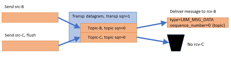
The publishing application sends a message to topic "B", this time without the "flush" flag. The source-side topic layer buffers the message. Then the publishing application sends a message to topic "C", with the "flush" flag. The source-side transport layer wraps both application messages into a single datagram and gives it transport sequence number 1, since it is the second datagram sent on the Transport Session. But the two topic level sequence numbers are 0, since these are the first messages sent to those topics.
Note that almost no latency is added by batching, so long as the second message is ready to send immediately after the first. This method of low-latency batching is called Intelligent Batching, and can greatly increase the maximum sustainable throughput of UM.
The subscriber gets the datagram and delivers the topic "B" message to the application receiver callback. It's topic-level sequence_number is 0 since it was the first message sent to the "B" source. However, the subscriber application has no receiver for topic "C", so the message "C" is simply discarded.
Example: UM Fragmentation <-
The publishing application now has a topic "A" message to send that is larger than the maximum allowable datagram.
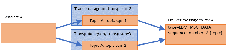
The source-side topic layer splits the application message into two fragments and assigns each fragment its own topic-level sequence number (1 for the first, 2 for the second). The topic-layer gives each fragment separately to the transport layer, which wraps each fragment into its own datagram, consuming two transport sequence numbers (2 and 3). Note that the transport layer does not interpret these fragments as parts of a single larger message; from the transport's point of view, this simply two datagrams being sent.
The receive-side transport layer gets the datagrams and hands them to the Topic-A Delivery Controller (receiver-side topic layer). The Delivery Controller reassembles the fragments in the correct order, and delivers the message to the application's receiver callback in a single call. The sequence_number visible to the application is the topic-level sequence number of the last fragment (2 in this example).
Note that the application receiver callback never sees a topic sequence_number of 1 for topic "A". It saw 0 then 2, with 1 seemingly missing. However, the application can call lbm_msg_retrieve_fragment_info() to find out the range of topic sequence numbers consumed by a message.
The behavior described above is for the default ordered_delivery (receiver) equal to 1. see Ordered Delivery for alternative behaviors.
Example: Loss Recovery <-
Now the publishing application sends a message to topic C. But the datagram is lost, so the receiver does not see it. Also, right after the send to topic C, the application deletes the sources for topics B and C.

Deleting a source shortly after sending a message to it is contrary to best practice. Applications should pause between the last send to a topic and the deletion of the topic, preferable a delay of between 5 and 10 seconds. This gives receivers an opportunity to attempt recovery if the last message sent was lost. We delete the sources here to illustrate an important point.
Note that although the datagram was lost and two topics were deleted, nothing happens. The receiver does not request a retransmission because the receiver has no idea that the source sent a message. Also, the source-side topic layer does not explicitly inform the receiver that the topics are deleted.
Continuing the example, the publishing application sends another message, this time a message for topic A ("Topic-A, topic sqn=3"):
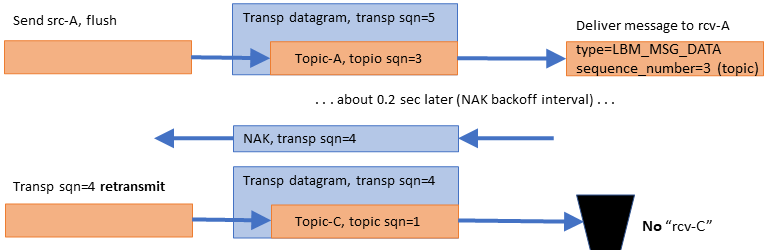
There are two notable events here:
-
The "A" message is delivered immediately to the topic "A" receiver, even though earlier data was lost and not yet retransmitted. If this were TCP, the kernel would buffer and prevent delivery of subsequent data until the lost data is recovered.
- The reception of that "A" message with transport sequence number 5 informs the receive-side transport layer that transport datagram #4 was lost. So it initiates a NAK/retransmission cycle. When the lost datagram is retransmitted, the receiver throws it away since it is for an unsubscribed topic.
You might wonder: why NAK and retransmit datagram 4 if the subscriber is just going to throw it away? The subscriber NAKs it because it has no way of knowing which topic it contains; if it were topic B, then it would need that datagram. The publisher retransmits it because it does not know which topics the subscriber is interested in. It has no way of knowing that the subscriber will throw it away.
Regarding message "Topic-A, sqn=3", what if the publisher did not have that message to send? For example, what if that "Topic-C, sqn=1" message were the last one for a while? This is called "tail loss" since the lost datagram is not immediately followed by a successful datagram. The subscriber has no idea that messages were sent but lost. In this case, the source-side transport layer would have sent a transport-level "session message" after about 200 ms of inactivity on the Transport Session. That session message would inform the receiver-side transport layer that datagram #5 was lost, and would trigger the NAK/retransmission.
Finally, note that the message for topic-C was retransmitted, even though the topic-C source was deleted. This is because the deletion of a source does not purge the transport layer's retransmission buffer of datagrams from that source. However, higher-level recovery mechanisms, such as late join and OTR, are no longer possible after the source is deleted. Also, if all sources on a Transport Session are deleted, the Transport Session itself is deleted, which makes even transport-level retransmission impossible. (Only Persistence allows recovery after the transport session is deleted.)
Example: Unrecoverable Loss <-
The previous examples assume that events are happening in fairly rapid succession. In this example of unrecoverable loss, significantly longer time periods are involved.
Unrecoverable loss is what happens when UM tries to recover the lost data but it is unable to. There are many possible scenarios which can cause recovery efforts fail, most of which involve a massive overload of one or more components in the data flow.
To simplify this example, let's assume that, starting now, all NAKs are blocked by the network switch. If the publisher never sees the NAKs, it assumes that all datagrams were received successfully and does not retransmit anything.
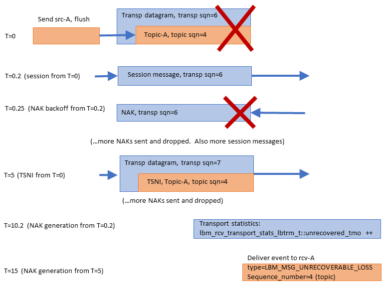
At T=0, the message "Topic-A, sqn=4" is sent, but not received. Let's assume that the publisher has no more application messages to send for a while. With every application message sent, the source starts two activity timers: a transport-level "session" timer, and a topic-level "TSNI" timer. The session timer is for .2 seconds (see transport_lbtrm_sm_minimum_interval (source)), and the TSNI timer is for 5 seconds (see transport_topic_sequence_number_info_interval (source)).
At T=0.2, the session timer expires and the source-side transport layer sends a session message. When the receive-side transport layer sees the session message, it learns that transport datagram #6 was lost. So it starts two receive-side transport-level timers: "NAK backoff" and "NAK generation". NAK backoff is shown here as .05 seconds, but is actually randomized between .025 and .075 (see transport_lbtrm_nak_initial_backoff_interval (receiver). The NAK generation is 10 seconds (see transport_lbtrm_nak_generation_interval (receiver)).
At T=0.25, the NAK backoff timer expires. Since the transport receiver still has not seen datagram #6, it sends a NAK. However, we are assuming that all NAKs are blocked, so the transport source never sees it. Over the next ~5 seconds, the source will send several more session messages and the receiver will send several more NAKs (not shown).
At T=5, the TSNI timer set by the source at T=0 expires. Since no application messages have been sent since then, the source sends a TSNI message for topic "A". This informs the Delivery Controller that it lost the message "Topic-A, sqn=4". However, the receive-side Delivery Controller (topic layer) does not initiate any recovery activity. It only sets a topic-level timer for the same amount of time as the transport's NAK generation timer, 10 seconds. The Delivery Controller assumes that the transport layer will do the actual data recovery.
At T=10.2, the receive-side transport layer's NAK generation timer (set at T=0.2) finally expires; the transport layer now considers datagram #6 as unrecoverable loss. The transport layer stops sending NAKs for that datagram, and it increments the receive-side transport statistic lbm_rcv_transport_stats_lbtrm_t_stct::unrecovered_tmo. Note that it does not deliver an unrecoverable loss event to the application.
Over the next ~5 seconds, the Delivery Controller continues to wait for the missing message to be recovered by the transport receiver, but the transport receiver has already given up. You might wonder why the transport layer doesn't inform the Delivery Controller that the lost datagram was unrecoverable loss. The problem is that the transport layer does not know the contents of the lost datagram, and therefore does not know which topic to inform. That is why the Delivery Controller needs to set its own NAK generation timer at the point where it detects topic-level loss (at T=5).
Note that had sources src-B and src-C not been deleted earlier, messages sent to them could have been successfully received and processed during this entire 15-second period. However, any subsequent messages for topic "A" would need to be buffered until T=15. After the unrecoverable loss event is delivered for topic A sequence_number 4, subsequently received and buffered messages for topic "A" are delivered.
Example: Transport Deletion <-
During the previous 15 seconds, the source-side had sent a number of topic-level TSNI (for topic A) and transport-level session messages. At this point, the publishing application deletes source "A". Since sources "B" and "C" were deleted earlier, "A" was the last source mapped to the Transport Session. So UM deletes the Transport Session.
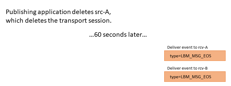
Note that no indication is sent from the source side to inform receivers of the removal of the sources, nor the Transport Session. So the receive-side transport layer has to time out the Transport Session after 60 seconds of inactivity (see transport_lbtrm_activity_timeout (receiver)).
The receive-side transport layer then informs both Delivery Controllers of the End Of Session event, which the Delivery Controllers pass onto the application receiver callback for each topic. The lbm_msg_t structure has an event type of LBM_MSG_EOS. The delivery controllers and the receive-side transport layer instance are then deleted.
However, note that the receiver objects will continue to exist. They are ready in case another publishing application starts up and creates sources for topics A and/or B.