DRO Configuration Overview <-
When the DRO daemon launches, it uses configuration option settings to determine its behavior and expectations. You specify option values in an XML configuration file, and reference the file from a command line argument.
Typically, you have a separate XML configuration file for each DRO, which contains structured configuration elements that describe aspects of the DRO. Within this XML configuration file, each endpoint portal definition points to a UM configuration file, which allow the portal to properly connect to its TRD.
Creating Applications for DRO Compatibility <-
When developing messaging applications that use Ultra Messaging and, in particular, the DRO, please observe the following guidelines.
Naming and Identification <-
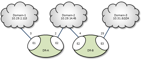
An important part to successfully implementing DROs is prudent and error-free naming of TRDs, DROs, portals, etc., as well as correct identification of IP addresses and ports. It is good practice to first design the DRO network by defining all connections and uniquely naming all DROs, portals, and TRDs. This works well as a diagram similar to some examples presented in this document. Include the following names and parameters in your design diagram:
- TRD names and IDs
- DRO names
- Portal names
- Portal costs
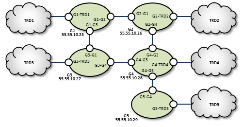
For example, a well-prepared DRO design could look like the following figure.
Portal Costs <-
A network of DROs uses forwarding cost as the criterion for determining the best (lowest cost) path over which to resolve a topic and route data. Forwarding cost is simply the sum of all portal costs along a multi-DRO path. Thus, total cost for the single path in the above example is 34. (Note that this is a non-real-world example, since costs are pointless without alternate routes to compare to.) You assign portal costs via the <cost> configuration option.
After the DRO network calculates its paths, if a new lower-cost source becomes available, receivers switch to that path.
Access Control Lists (ACL) <-
In the DRO, an Access Control List (ACL) is a method of blocking traffic from being forwarded from one TRD to another.
Typical applications for this feature are:
- Prevent unauthorized access to sensitive messages.
- Prevent overloading of bandwidth-limited WAN links, even in the face of accidental use of overly-permissive wildcard receivers.
- ACLs can be used to limit the amount of Topic Resolution traffic for topics on TRDs that don't need those topics. However, the use of wildcard receivers can result in TR traffic even for topics which are blocked from being forwarded.
You can apply Access Control Lists to one or more of a DRO's portals to filter traffic by topic, transport, transport session, etc. You configure an ACL in a DRO's XML configuration's <acl> element, as a child of an <endpoint> or <peer> portal. As messages are processed by the DRO, the portals use the ACLs to decide whether to reject the the messages or accept them.
Inbound vs. Outbound
There are two types of ACLs: inbound and outbound.
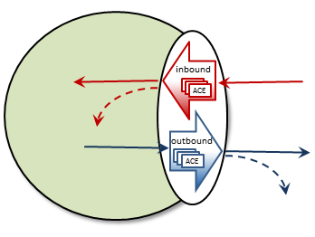
An inbound ACL tests messages from a source TRD on their way into a DRO portal, and decides whether to reject or accept them. If accepted, the messages can be forwarded to the appropriate destination portal(s).
An outbound ACL tests messages on their way out of a DRO portal, and decides whether to reject them, or transmit them to the destination TRD.
This distinction becomes especially important when a DRO has more than two portals. Messages rejected inbound cannot be forwarded at all. Messages rejected outbound can allow messages to be forwarded out some portals but not others.
An ACL contains one or more Access Control Entries (ACEs).
Access Control Entry (ACE)
An ACE specifies a set of message matching criteria, and an action to perform based on successful matches. The action is either accept (the message is made available for forwarding, based on interest) or reject (the message is dropped).
When more than one ACE is supplied in an ACL, messages are tested against each ACE in the order defined until a match is found, at which point the ACE specifies what to do (reject or accept).
An ACE contains one or more conditional elements.
Conditional Elements
Conditional elements do the work of testing various characteristics of messages to determine if they should be rejected or accepted (made available for forwarding).
When more than one conditional element is supplied in an ACE, received messages are tested against all of them to determine if the ACE should be applied.
There are two classes of conditional elements:
- Topic conditionals, which test the topic string of a message.
- Transport session conditionals, which test network transport session characteristics of a message.
Topic conditionals can be included on both inbound and outbound ACLs. The topic conditionals are:
- <topic> - tests for a specific topic name of messages,
- <pcre-pattern> - matches a group of topics according to a regular expression pattern,
- <regex-pattern> - deprecated, use <pcre-pattern> instead.
Transport session conditionals only apply to inbound ACLs (they are ignored for outbound). The transport session conditionals are:
- <transport> - tests the transport type of messages.
- <source-ip> - tests the IP address of the source or proxy source of messages.
- <multicast-group> - tests the destination multicast group of LBT-RM messages.
- <udp-destination-port> - tests the destination port of LBT-RM messages.
- <udp-source-port> - tests the source port of LBT-RM and LBT-RU messages.
- <tcp-source-port> - tests the source port of TCP messages.
- <xport-id> - tests the transport ID of LBT-IPC messages.
Conditional elements are children of the <ace> element. If you place multiple conditions within an ACE, the DRO performs an "and" operation with them. That is, all relevant conditions in the ACE must be true for the ACE to be applied to a message.
A portal will silently ignore conditional elements that don't apply. For example, if a transport conditional is used on an outbound ACL, or if a UDP-based conditional is present and a TCP message is received.
Reject by Default
An implicit "reject all" is at the end of every ACL, so the DRO rejects any topic not matched by any ACE. When an ACL is configured for a portal, rejection is the default behavior.
For example, to accept and forward only messages for topic ABC and reject all others:
No "reject" ACE is needed since rejection is the default.
In contrast, to accept all messages except for topic ABC:
The second ACE is used as a "match all", which effectively changes the default behavior to "accept".
ACE Ordering
Since the behavior for multiple ACEs is to test them in the order defined, ACEs should be ordered from specific to general.
In the example below, a user named "user1" is assigned to the LAN1 TRD. It is desired to forward all non-user-specific messages, but restrict user-specific message to only that user.
By ordering the ACEs as shown, messages for USER.user1 will be forwarded by the first ACE, but messages for USER.user2, etc. will be rejected due to the second ACE. Messages for topics not starting with "USER." will be forwarded by the third ACE.
Note that the string in "<topic>USER.user1</topic>" is not a regular expression pattern, and therefore does not need any special escaping or meta characters. The "<pcre-pattern>^USER\..*</pcre-pattern>" is a regular expression, and therefore needs the "^" anchor and the "\." escape sequence.
Timers and Intervals <-
The DRO offers a wide choice of timer and interval options to fine tune its behavior and performance. There are interactions and dependencies between some of these, and if misconfigured, they may cause race or failure conditions.
This manual's description of configuration options (see DRO Configuration Reference), includes identification of such relationships. Please heed them.
Multicast Immediate Messaging Considerations <-
Multicast Immediate Messages (MIMs) may pass through the DRO. You cannot filter MIMs with Access Control Lists (ACL)-MIMs are forwarded to all TRDs. Informatica does not recommend using MIM for messaging traffic across the DRO. MIM is intended for short-lived topics and applications that cannot tolerate a delay between source creation and the sending of the first message. See also Multicast Immediate Messaging.
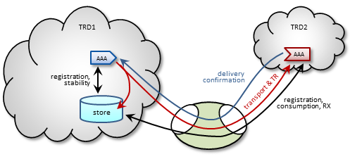
Persistence Over the DRO <-
The DRO supports UMP persistence by routing all necessary control and retransmission channels along with transport and topic resolution traffic. A typical implementation places the UMP persistent store in the same TRD as its registered source, as shown in the following figure.
The DRO also supports UMP implementations with the store located in a receiver's TRD, as shown in the following figure.
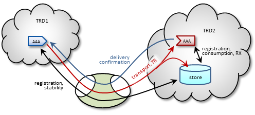
Note: For more reliable operation when using UMP with DROs, Informatica recommends enabling OTR.
Late Join and Off-Transport Recovery <-
The DRO supports sources and receivers configured for Late Join and/or Off-Transport Recovery (OTR). Retransmission requests and subsequent retransmissions are conducted across the entire path through the DRO network. A DRO's proxy sources do not have Late-Join/OTR retention buffers and hence, are not able to provide recovered messages.
Topic Resolution Reliability <-
Topic resolution can sometimes remain in a quiescent phase due to link interruption, preventing needed re-subscription topic resolution activity. Two ways you can address this are:
- For isolated incidents, call lbm_context_topic_resolution_request() (see example lbmtrreq.c). This restarts the sustaining phase.
- For more chronic problems, such as a DRO link (especially an endpoint link) over a WAN of questionable reliability, consider configuring Topic resolution to stay in the sustaining phase (options resolver_advertisement_minimum_sustain_duration (source) and resolver_query_minimum_sustain_duration (receiver)).
BOS and EOS Behavior Over the DRO <-
Through a network of DROs, a topic traverses a separate session for each link along its path. Thus, the DRO reports BOS/EOSs based on the activity between the proxy source transport and its associated receiver. There is no end-to-end, application-to-application reporting of the data path state. Also, in the case of multiple topics being assigned to multiple sessions, topics may find themselves with different session mates from hop to hop. Of course, this all influences when, and for which transport session, a topic's BOSs and EOSs are issued.
DRO Reliable Loss <-
The DRO can create a situation where a "reliable" transport (TCP or LBT-IPC) can experience out-of-order message delivery.
The DRO can perform a "protocol conversion" function. I.e. an originating source can use a UDP-based protocol (LBT-RM or LBT-RU), but the proxy source for a remote receiver can use a "reliable" protocol (TCP or LBT-IPC). With a UDP-based protocol, messages can arrive to the DRO network out of order, usually due to packet loss and recovery. However, when those out-of-order messages are forwarded across a "reliable" protocol (TCP or LBT-IPC), the receiver does not expect the sequence number gap, and immediately declares the out-of-order messages as unrecoverable loss. This, in spite of the fact that the missing message arrives shortly thereafter.
Starting in UM version 6.12, there are two new configuration options: transport_tcp_dro_loss_recovery_timeout (receiver) and transport_lbtipc_dro_loss_recovery_timeout (receiver), which modify the receiver's behavior. Instead of declaring a gap immediately unrecoverable, a delay is introduced which is similar to what a UDP-based receiver uses to wait for lost and retransmitted datagrams. If the missing message arrives within the delay time, the messages are delivered to application without loss.
Be aware that this functionality is only used with "reliable" protocols published by a DRO's proxy source. If this delay feature is enabled, it will not apply to a "reliable" protocol that is received directly from the originating source.
Note however that you can get genuine gaps in the "reliable" data stream without recovery. For example, an overloaded DRO can drop messages. Or a DRO's proxy receiver can experience unrecoverable loss. In that case, the delay will have to expire before the missing messages are declared unrecoverable and subsequent data is delivered.
- Attention
- The delay times default to 0, which retains the pre-6.12 behavior of immediately declaring sequence number gaps unrecoverable. If you want this new behavior, you must configure the appropriate option.
Topology Configuration Examples <-
Following are example configurations for a variety of DRO topologies. These are the topology examples presented Routing Topologies.
In a real-world situation, you would have DRO XML configuration files with their portal interfaces referencing complete UM configuration files. However, for these examples, the referred domain configuration files are simplified to contain only information relevant to the applicable DRO. As part of this simplification, domain configuration files show interfaces for only one or two transport types.
Also, IP addresses are provided in some cases and omitted in other cases. This is because initiator peer portals need to know the IP addresses (and port numbers) of their corresponding acceptor portals to establish connections, whereas endpoint portals communicate via topic resolution and thus, do not need to know IP addresses.
- Note
- Before designing any DRO implementations based on configurations or examples other than the types presented in this document, please contact UM Support.
Direct Link Configuration <-
This example uses a DRO to connect two topic resolution domain LANs.
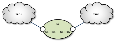
TRD1 Configuration
This UM configuration file, trd1.cfg, describes TRD1 and is referenced in the DRO configuration file.
G1 Configuration
This DRO configuration file defines two endpoint portals. In the daemon section, we have turned on monitoring for the all endpoint portals in the DRO. The configuration specifies that all statistics be collected every 5 seconds and uses the lbm transport module to send statistics to your monitoring application, which runs in TRD1. See also UM Concepts, Monitoring UMS. The Web Monitor has also been turned on (port 15304) to monitor the performance of the DRO.
TRD2 Configuration
The configuration file trd2.cfg could look something like this.
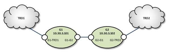
Peer Link Configuration <-
In cases where the DRO connection between two TRDs must tunnel through a WAN or TCP/IP network, you can implement a DRO at each end, as shown in the example below.
TRD1 Configuration
G1 Configuration
Following is an example of two companion peer portals (on different DROs) configured via DRO XML configuration file for a TCP-only setup. Note that one must be an initiator and the other, an acceptor.
G2 Configuration
TRD2 Configuration
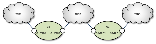
Transit TRD Link Configuration <-
This example, like the previous one, configures two localized DROs tunneling a connection between two TRDs, however, the DROs in this example are tunneling through an intermediate TRD. This has the added effect of connecting three TRDs.
TRD1 Configuration
G1 Configuration
Following is an example of two companion peer portals (on different DROs) configured via DRO XML configuration file for a TCP-only setup. Note that one must be an initiator and the other, an acceptor.
TRD2 Configuration
G2 Configuration
TRD3 Configuration
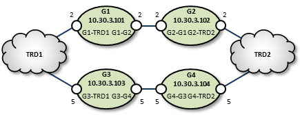
Parallel Links Configuration <-
This example is similar in purpose to the single link, peer-to-peer example, except that a second pair of DROs is added as a backup route. You can set one of these as a secondary route by assigning a higher cost to portals along the path. In this case we set G3 and G4's portal costs to 5, forcing the lower route to be selected only if the upper (G1, G2) route fails.
Also note that we have configured the peer portals for the leftmost or odd-numbered DROs as initiators, and the rightmost or even-numbered DRO peers as acceptors.
TRD1 Configuration
G1 Configuration
G2 Configuration
G3 Configuration
G4 Configuration
TRD2 Configuration
Loop and Spur Configuration <-
TRD1 Configuration
G1 Configuration
G2 Configuration
TRD2 Configuration
TRD3 Configuration
G3 Configuration
G4 Configuration
TRD4 Configuration
G5 Configuration
TRD5 Configuration
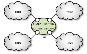
Star Configuration <-
This network consists of four TRDs. Within each TRD, full multicast connectivity exists. However, no multicast connectivity exists between the four TRDs.
G1 Configuration
The configuration for this DRO also has transport statistics monitoring and the WebMonitor turned on.
TRD1 Configuration
TRD2 Configuration
TRD3 Configuration
TRD4 Configuration
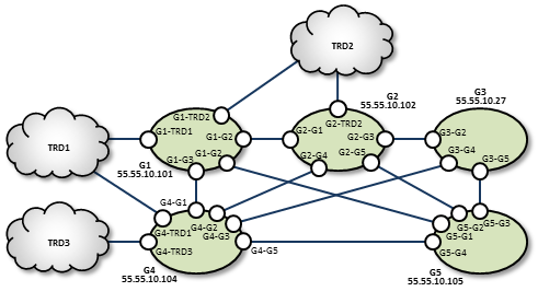
Mesh Configuration <-
The mesh topology utilizes many connections between many nodes, to provide a variety of alternate routes. However, meshes are not the best solution in many cases, as unneeded complexity can increase the chance for configuration errors or make it more difficult to trace problems.
TRD1 Configuration
G1 Configuration
G2 Configuration
G3 Configuration
TRD2 Configuration
TRD3 Configuration
G4 Configuration
G5 Configuration
Using UM Configuration Files with the DRO <-
Within the DRO configuration file, the endpoint portal's <lbm-config> element lets you import configurations from either a plain text or XML UM configuration file. However, using the XML type of UM configuration files provides the following advantages over plain text UM configuration files:
- You can apply UM attributes per topic and/or per context.
- You can apply attributes to all portals on a particular DRO using a UM XML template (instead of individual portal settings).
-
Using UM XML templates to set options for individual portals lets the DRO process these settings in the
<daemon>element instead of within each portal's configuration.
Setting Individual Endpoint Options <-
When setting endpoint options, first name the context of each endpoint in the DRO's XML configuration file.
Then assign configuration templates to those contexts in the UM XML configuration file.
You specify the unique options for each of this DRO's two endpoints in the UM XML configuration <templates> section used for G1-E1-options and G1-E2-options.
DRO and UM XML Configuration Use Cases <-
One advantage of using UM XML configuration files with the DRO is the ability to assign unique UM attributes to the topics and contexts used for the proxy sources and receivers (which plain text UM configuration files cannot do). The following example shows how to assign a different LBTRM multicast address to a source based on its topic.
Create a new UM XML configuration template for the desired topic name.
Then include this template in the <application> element associated with the DRO.
It is also possible to assign UM attributes directly in the <application> tag. For example, the following specifies that a particular topic should use an LBT-RU transport.
Sample Configuration <-
The following sample configuration incorporates many of the examples mentioned above. The DRO applies options to all UM objects created. The UM XML configuration file overwrites these options for two specific topics. The first topic, LBTRM_TOPIC, uses a different template to change its transport from TCP to LBTRM, and to set an additional property. The second topic, LBTRU_TOPIC, also changes its transport from TCP to a new value. However, its new attributes are applied directly in its associated topic tag, instead of referencing a template. In addition, this sample configuration assigns the rm-source template to all sources and receivers associated with the context endpt_1.
XML UM Configuration File <-
XML DRO Configuration File <-
This DRO uses the above XML UM configuration file, sample-config.xml, to set its UM options. It has three endpoints, one of which has the context endpt_1.
Running the DRO Daemon <-
To run the DRO, ensure the following:
- Library environment variable paths are set correctly (LD_LIBRARY_PATH)
- The license environment variable LBM_LICENSE_FILENAME points to a valid DRO license file.
- The configuration file is error free.
Typically, you run the DRO with one configuration file argument, for example:
(FYI: "tnwgd" stands for "Twenty Nine West Gateway Daemon", a historical name for the DRO.)
The DRO logs version information on startup. The following is an example of this information:
DRO NAT Transit <-
Some networks make use of a NAT router to map one IP address space onto another. If your network architecture includes LANs that are bridged with a NAT device, UM receivers will usually not be able to connect directly to UM sources across the NAT. Sources send Topic Resolution advertisements containing their local IP addresses and ports, but receivers on the other side of the NAT cannot access those sources using those local addresses/ports. They must use alternate addresses/ports, which the NAT forwards according to the NAT's configuration.
The recommended method of transiting a NAT is using two DROs connected via a peer link. The UM components in one network are organized as one TRD and the components in the other network are organized as a separate TRD.
There is an alternative method of transiting a NAT with UM using an lbmrd. This method reduces latency but has significant restrictions.
DRO NAT: TCP Peer <-
The simplest way to transit a NAT is to configure the DROs with Router Element "<single-tcp>". One DRO is configured to be the initiator and the other is the acceptor.
Many NAT designs restrict which network can initiate TCP connections across the NAT. The initiator DRO should be placed on the side that supports outgoing connections and configured for the IP address and port that the NAT router recognizes and forwards to the acceptor DRO. This may or may not be the IP address and port of the actual host running the acceptor DRO; contact your network support group for details.
DRO NAT: UDP Peer <-
DROs are sometimes configured to add UDP-based data transport. The TCP link is still used for command and control, so all the points made above still apply. In addition, the NAT must allow forwarding of bi-directional UDP traffic without modifying the destination port numbers.
Here's the sequence of events UM uses to establish communication:
-
The initiator DRO uses the configured address:port to initiate its TCP connection. Once established, the initiator sends DRO the UDP port it's accepting data on.
-
The acceptor DRO accepts the TCP connection, saves the UDP port of the initiator, and sends back it's own UDP port. The acceptor also examines the established TCP connection to determine the IP address of the initiator, and saves that. But note that due to the NAT, the IP address it determines will typically not be the initiator's host IP. Rather, it's an IP address of the NAT device, and the NAT will forward packets to the actual host running the initiator.
-
The initiator receives the acceptor's UDP port and saves it.
-
Now, when the initiator wants to send UDP data to the acceptor, it uses the configured IP and the saved UDP port as the UDP packet's destination IP/port.
- When the acceptor wants to send UDP data to the initiator, it uses the saved IP and UDP port.
Thus, for both the initiator and the acceptor, the configured UDP port is both used to locally bind the UDP socket, and used by the remote DRO as the UDP destination port. Thus, the NAT must not modify the destination port of UDP packets.
Some NAT designs do not expect this UDP behavior. Rather they perform a similar form of dynamic port allocation where a packet's source port is modified, and the networking software is expected to examine the source port and use it for outgoing packets. UM does not do that.
The NAT should be configured with static port mappings for all DRO peer links expected. If this is not practical, then UDP peer links may not be usable. Contact UM Support.