This section is about packet loss. It applies primarily to UDP-based network protocols used by UM: LBT-RM, LBT-RU, and UDP-based topic resolution.
(Packet loss also affects TCP-based protocols, but UM has no control over how it is handled by the IP stack. "Packet" loss can also happen with the IPC transport type if source-pacing is selected, but most of this section's discussion doesn't apply to IPC.)
Packet loss is almost always caused when some part of the system is receiving packets at a higher rate than it is able to process them. This might be a router, a switch, a subscribing host's kernel, or the subscribing process itself. This typically results in queuing of incoming packets within the router, switch, kernel, or socket buffer. But queues do not have unlimited size. If the incoming packets exceed the processing speed for too long a period of time, the queue will fill and packets will be dropped.
Packet loss is a fact of life in networks. Some users are able to provision and tune their systems such that they might only lose a few packets per week. Other users routinely live with several lost packets per minute. Many users do not monitor their system for loss and have no idea how frequent it is.
Packet loss is undesirable for many reasons. For reliable protocols (TCP, LBT-RM, etc), detection and retransmission of lost packets introduces significant latency. If packet rates are too high for too long a period of time, the transport protocol can give up trying to recover the lost data. For Streaming, this can cause disconnects or Unrecoverable Loss, where application messages can be lost forever.
Informatica recommends that you:
- Design your system to prevent packet loss.
- Configure UM for proper recovery from packet loss.
- Monitor your network for packet loss.
- Diagnose the cause of the observed packet loss and fine-tune your design and configuration to better prevent loss and optimize recovery from it.
Design to Prevent Loss <-
There are two complementary methods of avoiding packet loss:
Decrease Packet Flow through Loss Points <-
-
Message Batching. At most loss points, the number of packets is usually more important than the sizes of the packets. 100 packets of 60 bytes each is much more burdensome to packet consumers than 10 packets of 600 bytes each. For latency-sensitive applications, consider implementing an Intelligent Batching algorithm.
-
Reduce discards. Due to the way publishers map topics to Transport Sessions, it is often the case that the receiver will have to discard messages that it hasn't subscribed to. The LBT-RM transport statistics structure for each transport type contains the field "lbm_msgs_no_topic_rcved" which counts the number of data messages discarded. Also, the context statistics structure contains the field "lbtrm_unknown_msgs_rcved", which also counts data messages discarded.
For the LBT-RU transport type, you can get similar discards. See the LBT-RU transport statistics structure field "lbm_msgs_no_topic_rcved", and the context statistics structure field "lbtru_unknown_msgs_rcved".
For the TCP or LBT-RU transport types, you can often decrease discards by turning on Source Side Filtering.
With Multicast, the Source Side Filtering feature is not possible. So it is usually necessary to change the topic-to-transport session mapping. Ideally, this can be done by taking into account the topic interests of the subscribers. But often it simply means increasing the number of transport sessions. In the case of LBT-RM, increasing the number of multicast groups is preferred, but is often limited by the network hardware. In that case, you can multiply the number of transport sessions by varying the destination port.
Increase Efficiency of Packet Consumers <-
Here are some methods for increasing the efficiency of subscribers: Use a kernel-bypass driver. For Linux, use Receive Multiple Datagrams. Use Receive Buffer Recycling. For Java and .NET, use Zero Object Delivery.
UM Recovery of Lost Packets <-
See Messaging Reliability for a high-level description of message loss as it relates to UM.
UM recovers lost packets at multiple levels:
- Transport - TCP, LBT-RU, LBT-RM have low-level handshakes to detect and retransmit lost packets.
- OTR/Late Join - independent of transport, OTR and Late Join will recover data, typically after the transport layer is unable to recover.
- Persistence - closely-associated with OTR and Late Join, the persistent Store provides a much greater capacity to recover lost data. UM persistence provides a guarantee of message delivery, subject to a set of configurable constraints.
One common goal for most UM use cases is that users want the flow of new messages to continue unimpeded in parallel with recovery efforts of lost packets. Given that packet loss is almost always a result of high packet rates overloading one or more queuing points along a messaging path, the addition of packet recovery efforts can make the overload even worse. "Pouring gasoline on a fire" is an often-repeated metaphor.
Fortunately, packet rate overload tends to be temporary, associated with short-term traffic bursts. That is one reason why the UM lost packet recovery algorithms use time delays. For example: transport_lbtrm_nak_initial_backoff_interval (receiver) and otr_request_initial_delay (receiver). By waiting before requesting retransmissions, the burst is allowed some time to subside before we add retransmission to the normal traffic load. These delays do add to latency, but shortening the delay too much risks making the loss worse, which can make the overall latency worse than having a longer delay.
One limiting factor related to data recovery is UM's use of retransmission rate limits. After a short period of severe packet loss due to overload, many receivers will be requesting retransmission. It would make no sense for the initial request delay to successfully bypass the original traffic burst, only to create its own overloading burst of retransmissions. Older NAK-based systems can get into a positive feedback loop where loss leads to retransmission, which leads to more loss, which leads to more retransmission, etc. Even once new data rates return to normal, networks can be locked into this kind of NAK/Retransmission storm. UM's retransmission rate limiter throttles the retransmission of lost packets over time without worsening the loss.
Another limiting factor related to data recovery is the amount of data which the sender buffers and is available for retransmission. Applications need to continue sending new data while recovery takes place. Since the buffer is of limited size, older buffered messages will eventually be overwritten with new messages.
For streaming applications, these buffers are held in memory, and the sizes are usually measured in megabytes. For persistent applications, the Store writes its buffer to disk, allowing for buffer sizes orders of magnitude larger than memory-based buffers. But even the Store's disk-based buffer is of finite size, and is susceptible to being overwritten if it takes too long to recover data.
Note that the Receiver Paced Persistence (RPP) feature seeks to maximize the reliability of messaging by allowing the publisher to be blocked from sending rather than overwriting unacknowledged data.
Given these limiting factors for data recovery, a sufficiently-overloaded network can reach a point where lost data can no longer be recovered, a situation called "unrecoverable loss".
Finally, it is very important for UM users to make use of UM's extensive monitoring capabilities. Since UM does a good job of recovering lost packets, you may be experiencing high latency spikes without knowing it. And recovered loss today can be a warning of unrecoverable loss tomorrow. User are strongly advised to monitor transport statistics and pay special attention to receivers that repeatedly experience loss. Even if that loss is successfully recovered, you should diagnose and treat the loss before it gets worse and becomes unrecoverable.
See Monitoring for more information.
Packet Loss Points <-
There are just a few common points at which packets are normally lost:
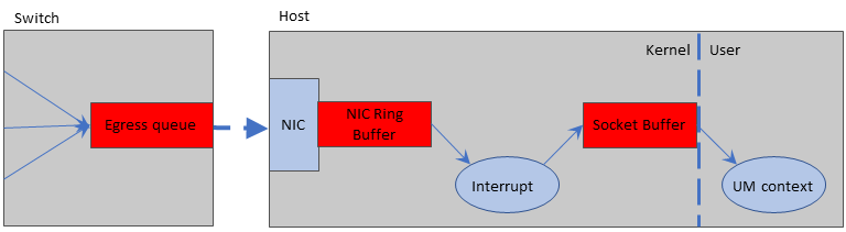
The red buffers/queues are the most common locations where packets are typically lost during a packet burst.
Loss: Switch Egress Port <-
The switch egress port can come under pressure if data flows from multiple sources need to be merged onto a single outgoing link. The outgoing link can be an internal trunk or communication link connecting two pieces of network equipment, but more typically it is link to a destination host.
It is easy to understand how loss can happen here. Suppose three remote hosts are sending UDP data streams at the destination host. If each stream is carrying 0.5 gigabit/sec of throughput, the switch needs to send 1.5 gigabit/sec over a 1 gigabit link, a clear overload. If this is a very short-term burst, the egress queue will hold the data until the incoming data flows subside and the outgoing port can get caught up. But if the burst lasts too long and the egress queue fills, the switch has no choice but to drop packets.
Note that the switch will not count these drops as "errors". There is a separate drop counter which should be examined to diagnose switch egress port loss.
The only solution is to reduce the packet rate being sent to the destination host. See Decrease Packet Flow through Loss Points.
Loss: NIC Ring Buffer <-
As packets are received by the host's NIC (Network Interface Card), they are copied into host memory in a structure called the Receive Ring Buffer. The NIC interrupts the OS, which has the responsibility to unload the packet buffers from the Ring Buffer. If the incoming packet rate is faster than the OS can unload the Ring Buffer, it will fill and packets will be dropped.
Normally, the kernel is able to service NIC interrupts without any trouble. However, there is one situation which can put the Ring Buffer under pressure: When multiple processes on the host are subscribed to the same multicast stream, the kernel must replicate and deliver the packets to each process. For a small number of processes (5-10), the kernel will still be able to keep up with the incoming packets.
However, as companies consolidation servers by moving to large, many-core hosts (often virtualized), we see the same multicast stream subscribed to by increasing numbers of processes on the same physical server. We have seen NIC Ring Buffer loss (also called "overrun") with as few as 15 processes subscribed to a heavy stream of multicast packets.
(Note that this is generally only a problem for multicast. With Unicast data distribution to many recipients, the source essentially does the packet replication work. The receive-side work for the kernel for each unicast packet is minimal.)
Users should maximize the size of the NIC's Receive Ring Buffer. For many NICs, the size of the ring buffer is configured by the number of receive descriptors. This should be set to the maximum allowable value.
The mitigators listed in Loss: Switch Egress Port will also help this problem by reducing the incoming packet rate.
Another solution is to spread processes across more physical hosts. This has the additional advantage of reducing latency, since multicast replication within a host must be done in software by the kernel and is serial in nature, whereas replication in the network is done by specialized hardware in parallel.
Another possible solution involves the use of the DRO as the primary receiver of the multicast data, which then re-publishes it on the host using the IPC transport. This has the disadvantage of introducing some additional latency since the messages must be received by the DRO and then forwarded to the application receivers. It also requires separating the applications to their own Topic Resolution Domains (TRDs).
Onload users can get more information at Solarflare Tips.
Loss: Socket Buffer <-
The Socket Buffer represents the interface between the OS kernel and the user process. Received data is transferred from the NIC Ring Buffer to the destination Socket Buffer(s). The Socket Buffers are then emptied by the application process (in this case, the UM Context Thread). Socket buffer sizes are configurable, according to the transport type. For example, see transport_lbtrm_receiver_socket_buffer (context).
The TCP protocol is designed to ensure that the socket buffer cannot be overflowed. However, UDP-based protocols (LBT-RU and LBT-RM) are susceptible to socket buffer overflow, which leads to datagram loss.
All of the mitigators listed Loss: NIC Ring Buffer will help this problem by reducing the incoming packet rate.
An obvious mitigator is to increase the sizes of the receive socket buffers. Informatica usually recommends at least 8MB for UDP-based protocols. But this only works if the problem is related to short-term traffic bursts. Simply increasing the size of the buffer will not avoid loss if the average message rate exceeds the average consumption and processing rate of the receiving program.
A very useful method for mitigating socket buffer loss is to increase the efficiency of the receiving application. The Receive Multiple Datagrams can increase that efficiency without sacrificing latency.
Also, the Transport Services Provider (XSP) feature can help by splitting the work of unloading multiple sockets across multiple threads.
Loss: Other <-
The three loss locations described above are all related to high packet rates causing fixed-sized packet buffers to overflow. These represent by far the most common reasons for packet loss. However, it is possible that you will experience loss that cannot be diagnosed to those three causes.
For example, we have seen reports of NIC hardware malfunctioning such that most packets are successfully received and delivered, but some percentage of packets fail. At least one user reported that a misconfigured router "flapped" a route, resulting in periodic, short-term loss of connectivity between two sub-networks. We have seen a case where the use of kernel bypass drivers for high-performance NICs (specifically Solarflare) can cause multicast deafness if both accelerated and non-accelerated processes are run on the same host. We have even seen a case where replacing the Ethernet cable between a host and the switch resolved packet loss.
It is not possible to have a step-by-step diagnostic procedure which will pinpoint every possible cause of packet loss. The techniques described in this document should successfully diagnose a large majority of packet loss causes, but nothing can replace your infrastructure network engineers expertise at tracking down problems.
Verifying Loss Detection Tools <-
The preceding techniques for mitigating loss are best deployed after you have identified the type of loss. Unfortunately, we have found that the tools available to detect and identify the location of loss to be problematic. Informatica does not provide such tools, and does not follow the market for such tools to find a reliable supplier.
However, we have a starting point that has given us some measure of success in diagnosing the loss points. It is important that you try out these tools to verify that they properly detect the different types of loss. In order to verify them, you need to be able to reproduce on demand loss at each of the points: switch, NIC, and socket buffer.
Fortunately, this is reasonably easy using the msend and mdump tools provided in the "mtools" package offered by Informatica free of charge. Download the mtools package from https://community.informatica.com/solutions/informatica_mtools The source files for msend and mdump are provided, as well as pre-built binaries for most major platforms.
Informatica recommends verifying your loss diagnosis tools before you have a serious loss event that disrupts your application system, preferably before your system goes into full production usage. Periodically running and recording the results of these tools during normal operation will make it possible to diagnose loss after the fact. Detecting and identifying non-severe (recoverable) loss can be used to prevent serious (unrecoverable) loss events in the future.
Prepare to Verify <-
- Download and install mtools on two hosts, designated "sender" and "receiver". Informatica recommends that the hosts be "bare metal" (not virtual machines), and that they be connected to the same switch. This minimizes the chances that the verification tests will cause any disruption to normal operation.
- Contact your system and network administrators and set up some time that they can work with your during the verification process. They will need to perform operations that you probably do not have the ability to do.
- Have the network administrator allocate a multicast group that you can use for this test. That multicast group should be otherwise unused in your organization. Warn the administrator that you will be pushing intense traffic bursts between the two hosts.
Verifying Switch Loss <-
A possible Unix command that a network administrator could use is:
snmpwalk -v 1 -c public SWITCH_ADDR IF-MIB::ifOutDiscards
Note that the above community string ("public") is probably not enabled; the network administrator will know the appropriate value. Ideally, the network administrator would run that command every 5 or 10 minutes, logging to a file, with a time stamp. If this log file could be shared read-only to the project groups, they can time-correlate any unusual application event with loss reported by the switch.
To verify that you properly detect switch loss, follow these steps:
- Work with your system and network administrators to enable Ethernet flow control in both the switch port and the NIC.
-
Use the above
snmpwalkcommand (or equivalent) to record the current drop counts for the switch ports. -
On the receiving host, run 30 copies of the following command:
mdump -qMCAST_ADDR12000INTFC_ADDR
where MCAST_ADDR is the multicast group for the test, and INTFC_ADDR is the IP address of the receiving host. -
On the sending host, run the following command:
msend -5MCAST_ADDR12000 15INTFC_ADDR
where MCAST_ADDR is the multicast group for the test, and INTFC_ADDR is the IP address of the sending host. -
When the test completes, use the
snmpwalkcommand again (or equivalent) to record another set of drop counters. The receiving host's drop count should be larger.
This test works by making the receiving host's kernel work very hard for each received datagram. It should be unable to keep up. (If you don't see any drops caused by the test, try doubling the number of copies of mdump on the receiving host.) The Ethernet flow control settings on the NIC and switch will prevent NIC loss in its ring buffer by slowing down the switch's egress port. Thus, the switch's egress queue will fill and should overflow.
Verifying NIC Loss <-
Unix
On some Unix systems, the "ifconfig" command will accurately report receive overrun on the NIC. For example:
ifconfig eth0
But in many Unix systems, the values reported by "ifconfig" remain at zero, even when the NIC has in fact overrun its receive ring buffer. We recommend also trying the "ethtool" command. For example:
ethtool -s eth0
Windows
To the best of our knowledge, there is no standard Windows tool for detecting NIC loss. Some drivers might provide that information from the interface control panel. Otherwise, you might need to download a management application from the NIC or system vendor.
If you know of a widely-available method to detect NIC overrun on Windows, please let us know at our DLMessagingBuilds email account on informatica.com (that awkward wording used to avoid spam address harvesters).
To verify that you properly detect NIC loss, follow these steps:
- Work with your system and network administrators to disable Ethernet flow control in both the switch port and the NIC.
- Use your NIC loss tool to get the current receive overrun count.
-
On the receiving host, run 30 copies of the following command:
mdump -qMCAST_ADDR12000INTFC_ADDR
where MCAST_ADDR is the multicast group for the test, and INTFC_ADDR is the IP address of the receiving host. -
On the sending host, run the following command:
msend -5MCAST_ADDR12000 15INTFC_ADDR
where MCAST_ADDR is the multicast group for the test, and INTFC_ADDR is the IP address of the sending host. - When the test completes, use the NIC loss tool again to record the receive overrun count.
This test works by making the receiving host's kernel work very hard for each received datagram. It should be unable to keep up. (If you don't see any drops caused by the test, try doubling the number of copies of mdump on the receiving host.) The lack of Ethernet flow control means that the switch will send the packets at full line rate, which should overflow the NIC ring buffer.
Verifying Socket Buffer Loss <-
On most systems, the netstat command can be used to detect socket buffer overflow. For example:
netstat -s
Look in the UDP section for "receive errors". This normally represents the number of datagrams dropped due to the receive socket buffer being full.
Note that Windows prior to version 7 does not increment that field for socket buffer overflows. If you have pre-Windows 7, we don't know of any command to detect socket buffer overflow.
To verify that you properly detect socket buffer overflow, follow these steps:
-
Use
netstat -sto get the current receive error count. -
On the receiving host, run a single copy of the command:
mdump -q -p1000/5MCAST_ADDR12000INTFC_ADDR
where MCAST_ADDR is the multicast group for the test, and INTFC_ADDR is the IP address of the receiving host. -
On the sending host, run the following command:
msend -5 -s2200MCAST_ADDR12000 15INTFC_ADDR
where MCAST_ADDR is the multicast group for the test, and INTFC_ADDR is the IP address of the sending host. -
When the test completes, use
netstat -sagain to get the new receive error count.
This test works by introducing a short sleep in the "mdump" command between reception of datagrams. This causes the socket buffer to overflow.
TCP Disconnections <-
The TCP protocol is generally very good at recovering from periods of packet loss. However, if no packets at all can get through for an extended period, TCP will reach its retry limit and disconnect. This can affect the TCP transport and UIMs.
This can happen if there is a network fault that lasts for an extended period.
Another potential root cause of TCP disconnections can be a stateful firewall. These devices monitor traffic on active TCP connections and will time out idle connections if no packets are sent for a configurable period, typically measured in minutes. The firewall typically does not inform the hosts using the TCP connection, so the hosts think the connection is still valid. However, when the sending host tries to transmit, the firewall will simply drop the packets, leading to the sender timing out the TCP connection and disconnecting.
Note that the other side of the connection often does not detect this disconnection, leading to a half-open connection. For the TCP transport, this can prevent a receiver from restarting topic resolution, which can be necessary for the receiver to recover from a temporary outage.
One solution to this problem is to enable TCP keepalives by setting transport_tcp_activity_method (receiver) to "SO_KEEPALIVE" and transport_tcp_activity_timeout (source) to a greater-than-zero value for TCP transports, and setting request_tcp_activity_timeout (context) and response_tcp_activity_timeout (context) to greater-than-zero values for UIMs. These keepalives prevent the firewall from timing out a quiet TCP connection, or if the connection is lost for some other reason, will inform both hosts in a timely fashion.