2. Conceptual View
The UM Gateway bridges disjoint topic resolution domains by effectively forwarding multicast and/or unicast topic resolution traffic, such as topic advertisements and queries (TIR/TQR), across gateways.
This section discusses the following topics.
2.1. UM Gateway Portals
A UM Gateway consists of two or more bidirectional portals that may be one of two types:
-
An endpoint portal that communicates directly to a UM topic resolution domain.
-
A peer portal that communicates only with another peer portal (of another gateway), allowing tunneling behavior between gateways or other portals.
You configure portals in the gateway's XML configuration file, specifying the portal's name, cost, UM Configuration, Access Control Lists and other attributes. See UM Gateway Configuration for more.
2.2. Topic Resolution Domains
UM contexts must satisfy the following two requirements to belong to the same topic resolution domain.
-
The contexts must use the same topic resolution UM configuration (i.e., resolver_* options are the same).
-
Contexts can communicate using the protocols required for both message transport and topic resolution traffic.
For example, two contexts on separate machines in the same LAN are not in the same topic resolution domain if they use different resolver addresses. See Multicast Resolver Network Options. A topic resolution domain can span a WAN if the UM contexts on each side of a firewall use the same UM configuration and the firewall allows UDP traffic (multicast or unicast) to pass.
Each endpoint portal must identify its associated topic resolution domain with a domain-id in the gateway's XML configuration file, as in the example below. All portals in the same topic resolution domain must have the same domain-id.
  <portals>
    <endpoint>
      <name>LAN100</name>
      <domain-id>100</domain-id>
      <lbm-config>lan100.cfg</lbm-config>
    </endpoint>
    <endpoint>
      <name>LAN200</name>
      <domain-id>200</domain-id>
      <lbm-config>lan200.cfg</lbm-config>
    </endpoint>
  </portals>
2.3. Basic Gateway Topology and Operation
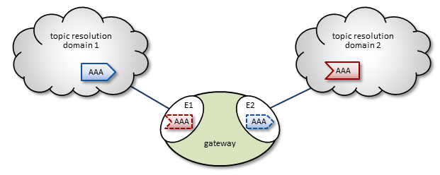
The diagram, UM Gateway, shows a UM Gateway bridging topic resolution domain 1 and topic resolution domain 2, for topic AAA. Endpoint E1 contains a proxy receiver for topic AAA and endpoint E2 has a proxy source for topic AAA.
2.3.1. Topic Resolution Across the Gateway
To establish topic resolution in an already-running UM Gateway, the following typically occurs in an example like the above figure.
-
A receiver in topic resolution domain 2 issues a TQR for topic AAA.
-
Portal E2 receives the TQR and requests that portal E1 find a TIR for AAA on topic resolution domain 1. At this point, we can say that interest for topic AAA has been discovered within the gateway.
-
E1 immediately responds with three actions: a) create a proxy receiver for topic AAA, which b) sends a TQR for AAA on domain 1, and c) issues a Topic Interest message for the benefit of any other portals that may exist in this gateway.
-
A source for topic AAA in domain 1 issues a TIR.
-
E1's AAA proxy receiver requests that E2 (and any other portals in the gateway) create a proxy source for AAA.
-
E2 creates proxy source AAA and issues a TIR to domain 2, thus completing topic resolution.
2.3.2. Interest and Use Queries
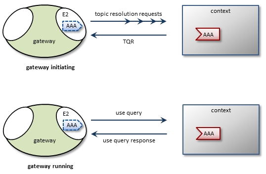
When a UM Gateway first starts, its endpoint portals issue a brief series of Topic Resolution Request messages to their respective topic resolution domains. This provokes quiescent receivers (and wildcard receivers) into sending TQRs, indicating interest in the various topics. Each portal then records this interest. The gateway uses a periodic purge cycle to detect when there is no longer any interest in the topic (i.e. all receivers for a topic have been deleted), and removes it from the portals.
After a gateway has been running, endpoint portals issue periodic Topic Use Queries and Pattern Use Queries (collectively referred to as simply Use Queries). Use Query Responses from UM contexts confirm that the receivers for these topics indeed still exist, thus maintaining these topics on the interest list. Autonomous TQRs also refresh interest and have the effect of suppressing the generation of Use Queries.
In the case of multi-hop gateway configurations, gateways cannot detect interest for remote contexts via Use Queries or TQRs. They do this instead via Interest Messages. A portal generates periodic interest messages, which are picked up by adjacent gateways (i.e., the next hop over), at which time interest is refreshed.

Intervals, limits, and durations for these topic resolution and interest mechanisms can be adjusted via gateway configuration options (see UM Gateway Configuration).
2.3.3. Gateway Keepalive
To maintain a reliable connection, gateways exchange Gateway Keepalive signals when connected via peer portals. Keepalive intervals and connection timeouts are configurable, and you can also set the gateway to send keepalives only when traffic is idle (default). See <gateway-keepalive>.
2.3.4. Proxy Sources and Receivers
The domain-id is used by Interest Messages and other internal and gateway-to-gateway traffic to ensure forwarding of all messages (payload and topic resolution) to the correct recipients. This also has the effect of not creating proxy sources/receivers where they are not needed. Thus, gateways create proxy sources and receivers based solely on receiver interest.
If more than one source sends on a given topic, the receiving portal's single proxy receiver for that topic receives all messages sent on that topic. The sending portal, however creates a proxy source for every source sending on the topic. The UM Gateway maintains a table of proxy sources, each keyed by an Originating Transport ID (OTID). This enables proxy receiver to forward each message to the correct proxy source.
Note: UM sources create a unique OTID that describes their transport sessions and include this OTID in their topic advertisements. For more on multiple sources, see Resolver Cache's Stored Cost Values Prevents Duplicates
Note: It is important to keep maximum datagram sizes exactly the same across all topic resolution domains and transports. For example, if the topic resolution domain on one side of a gateway uses LBT-RM message transport and the topic resolution domain on the other side uses LBT-RDMA, fragments from domain 1 will be too large for domain 2. See transport_*_datagram_max_size in the UM Configuration Guide.
2.3.5. Multi-Hop Forwarding
Consider a simple example UM Gateway deployment, as shown in Multi-Hop Network Example.
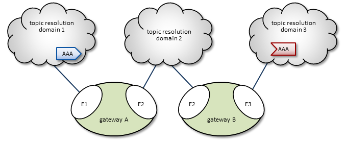
In this diagram, gateway A has two endpoint portals, connected to topic resolution domains 1 and 2. gateway B also has two endpoint portals that bridge domains 2 and 3. (Endpoint portal names reflect the topic resolution domain to which they connect. For example, gateway A endpoint E2 interfaces topic resolution domain 2.)
Topic resolution domain 1 has a source for topic AAA, and domain 3, an AAA receiver. The following sequence of events enables the forwarding of topic messages from source AAA to receiver AAA.
-
Receiver AAA queries (issues a TQR) for a source.
-
Gateway B, endpoint E3 (B-E3) receives the TQR and requests that any other portals in the gateway forward any AAA advertisements.
-
In response, B-E2 creates a proxy receiver for AAA and sends a Topic Interest message for AAA to topic resolution domain 2. (The proxy receiver also issues a TQR.)
-
Gateway A, endpoint E2 (A-E2) receives this Topic Interest message and requests that any other portals in the gateway forward any AAA advertisements.
-
In response, A-E1 creates a proxy receiver for AAA and sends a Topic Interest message (and TQR) for AAA to domain 1.
-
Source AAA responds to the TQR by sending a TIR for topic AAA.
-
The AAA proxy receiver created by A-E1 receives this TIR and requests that all gateway A portals with an interest in topic AAA create a proxy source for AAA.
-
In response, A-E2 creates a proxy source which sends a TIR for topic AAA via domain 2.
-
The AAA proxy receiver created by B-E2 receives this TIR and requests that all gateway B portals with an interest in topic AAA create a proxy source for AAA.
-
In response, B-E3 creates a proxy source, which sends a TIR for topic AAA via domain 3.
-
Topic AAA has now been resolved across both gateways, which forward all topic messages sent by source AAA to receiver AAA.
Note: Access Control Lists can alter this sequence by, for example, accepting only certain transport types or forwarding only certain topics. For more, see Access Control Lists (ACL).
2.4. Forwarding Costs
Forwarding a message through a gateway incurs a cost in terms of latency, network bandwidth, and CPU utilization on the gateway machine, which may in turn affect the latency of other forwarded messages. Transiting multiple gateways adds even more cumulative latency to a message. Other gateway-related factors such as network bandwidth, switches, etc., can also add latency.
Factors other than latency contribute to the cost of forwarding a message. Consider a message that can be sent from one domain to its destination domain over one of two paths. A three-hop path over 1000Mbps links may be faster than a single-hop path over a 100Mbps link. Further, it may be the case that the 100Mbps link is more expensive or less reliable. These could all be reasons for favoring the longer path.
To account for these cost factors, topic advertisements (TIR) contain the following two fields.
-
hop count
-
cost
These fields appear as topic options within the TIR. When you call lbm_src_create(), UM sets both to 0 (zero) for use by the UM Gateway. You cannot set these fields; they are populated automatically by the gateway(s).
2.4.1. Hop Count
When the egress portal of a gateway creates a proxy source to forward, in effect, the original source's topic advertisement, it increments the hop count by one. In the Multi-hop example presented earlier, gateway A, endpoint E2 (A-E2) and gateway B, endpoint E3 (B-E3) would each increment the hop count, resulting in receiver AAA receiving a TIR with a hop count = 2.
2.4.2. Portal Costs
The UM Gateway lets you assign a cost to a portal. As with the hop count, when a portal creates a proxy source, it adds the portal's configured cost to the topic cost in the TIR. By default, the cost associated with a portal is 0. Using the Multi-hop example again, setting portal A-E2's cost to 3 increases the topic's cost by that much. If portal B-E3's cost is 2, the topic's cost (and TIR cost), as received by receiver AAA, is now 5. The UM Gateway uses the cost to ensure that proxy receivers connect via the most efficient path to/from their source.
Note: After paths are established, if a new lower-cost source becomes available, receivers do not switch to it.
2.4.3. Resolver Cache's Stored Cost Values Prevents Duplicates
The UM Resolver Cache stores TIRs to help receivers find sources. In addition to transport session information, the stored TIR contains the OTID, hop count and cost values. This information can be used by receivers to select the lowest cost source if a source sends over multiple network paths.
In more complex network topologies, messages from the same source may traverse multiple paths and therefore, arrive from different proxy sources and different transport sessions. If a receiver looks up a topic in the cache and finds two TIRs with the same OTID but different transport sessions, it chooses the OTID with the lowest cost and joins that transport to receive messages. This prevents receiving duplicate messages from the same source.
A UM receiver always treats advertisements for the same topic with the same OTID as equivalent transport sessions, and joins only one of them. In the event that the receiver detects an EOS on the joined transport session, one of any remaining equivalent transport sessions can be joined.
For Multicast Immediate Messages (MIM) traffic, UM receivers keep a sequence number map for every OTID they have received messages from and reject any messages that have already been received.
2.4.4. Applications Can Also Set the Topic Cost
Your application can change the cost of a topic in the receiving application's context using a callback ( source_cost_evaluation_function) that the UM Gateway uses in lbm_src_cost_function_cb(). The gateway invokes this function whenever it receives an advertisement containing cost information. With a multiple-path topology, the gateway always forwards advertisements and messages via the least costly path, using lbm_src_cost_function_cb() to determine the cost.
You can supply a callback with source_cost_evaluation_function to affect this cost determination, increasing the cost of less desirable paths or completing filtering out certain paths. The gateway passes the topic name, hop count, and cost to the configured callback, which returns an integral cost value the gateway assigns to the topic. If you do not set source_cost_evaluation_function, a default function returns the cost as passed to it.
Note: Your gateway application cannot directly configure the cost in a TIR; this is done by only the gateway itself.
2.5. Access Control Lists (ACL)
You can apply Access Control Lists (ACL) to a gateway's portals to filter or load balance traffic by certain topics, transports, topic patterns, multicast groups, etc. You configure ACLs in a gateway's XML configuration file, as children of an <endpoint> or <peer> portal. As traffic arrives at the portal, the portal either forwards it or rejects it per ACL criteria.
Inbound ACLs determine what information to forward to other portals in the gateway, while Outbound ACLs determine (by topic) what information from other portals that this portal can forward out the gateway. Each portal (endpoint or peer) can have up to one inbound ACL and one outbound ACL.
An ACL can contain one or more Access Control Entries (ACEs). ACEs let you match (and accept or reject based on), criteria elements called Access Control Conditions (ACCs). Possible ACCs are:
-
<multicast-group/> *
-
<pcre-pattern> (PCRE wildcard patterns)
-
<regex-pattern> (Regex wildcard patterns)
-
<source-ip/> *
-
<tcp-source-port/> *
-
<topic>
-
<transport/> *
-
<udp-destination-port/> *
-
<udp-source-port/> *
-
<xport-id/> * (for LBT-IPC traffic)
* These items apply to only inbound ACLs, and are ignored if used with an outbound ACL.
The above elements are all children of the <ace> element. When an ACL has multiple ACE entries, the UM Gateway goes down the list until it finds a match. It then accepts (forwards) or rejects, and is done with that ACL. An implicit "reject all" is at the end of every ACL, so the UM Gateway rejects any topic not matched. If you place multiple ACCs within an ACE, the gateway performs an "and" operation with them.
Note that the portal ignores an ACC if a) it is inbound-only and used in an outbound ACL, or b) it simply does not apply (such as a <udp-source-port/> if the transport is TCP).
Consider the following example, where we configure a portal to forward on specific topics. This example also illustrates the parent/child hierarchy for ACLs, ACEs, and ACCs.
    <endpoint>
      <name>LAN1</name>
      <lbm-config>lan1.cfg</lbm-config>
      <domain-id>1</domain-id>
        <acl>
          <inbound>
            <ace match="accept">
              <topic>ABC</topic>
            </ace>
            <ace match="accept">
              <topic>DEF</topic>
              <transport value=lbt-rm comparison=eq/>
            </ace>
            <ace match="accept">
              <topic>GHI</topic>
            </ace>
          </inbound>
        </acl>
    </endpoint>
The above example shows each topic match in a separate ACE. When topic "GHI" arrives, the portal finds a match in the third ACE and forwards the topic. (Placing all three <topic>s in a single ACE would never match anything.) Also note that "DEF" is forwarded only if it uses an LBT-RM transport.
Since the behavior for multiple ACEs is "first match, then done", list ACEs in a specific-to-general order. For the example below, to forward topic "ABC123" but reject similar topics such as "ABCD123" or "ABCE123", list the ACE for "ABC123" first (as done below). If the ACE to reject "ABC.*123" was listed first, it would also (undesirably) match and reject "ABC123".
    <endpoint>
      <name>LAN1</name>
      <lbm-config>lan1.cfg</lbm-config>
      <domain-id>1</domain-id>
        <acl>
          <inbound>
            <ace match="accept">
              <topic>ABC123</topic>
            </ace>
            <ace match="reject">
              <pcre-pattern>ABC.*123</pcre-pattern>
            </ace>
          </inbound>
        </acl>
    </endpoint>
You could also filter on certain transport types to accept multicast traffic but reject tcp traffic, as shown below.
    <endpoint>
      <name>LAN1</name>
      <lbm-config>lan1.cfg</lbm-config>
      <domain-id>1</domain-id>
        <acl>
          <inbound>
            <ace match="accept">
              <transport comparison="equal" value="lbtrm"/>
            </ace>
            <ace match="reject">
              <transport comparison="equal" value="tcp"/>
            </ace>
          </inbound>
        </acl>
    </endpoint>
2.6. Response Forwarding
For request/response, the gateway appears as the responder from the perspective of the requester, and as the requester from the perspective of the responder. The UM Gateway supports request/response directly by maintaining a map between the original requester and the proxy request object it creates. The UM Gateway modifies requests and responses to appear as if they originated from the gateway.
2.7. Multicast Immediate Messaging Considerations
Multicast Immediate Messages (MIM) flood through the UM Gateway. You cannot filter MIM with Access Control Lists (ACL). Receivers on the other side of the gateway can easily receive duplicate messages. Informatica does not recommend using MIM for messaging traffic across the UM Gateway. MIM is intended for short-lived topics and applications that cannot tolerate a delay between source creation and the sending of the first message. See also Multicast Immediate Messaging.
2.8. Wildcard Receivers
The UM Gateway supports wildcard receivers, provided wildcard topic querying is not disabled. The gateway processes wildcard queries, replicating the functionality in the UM topic resolution wildcard processing. The UM Gateway creates a single proxy receiver for each topic, including topics that match one or more wildcard patterns.
2.9. TCP Connections for Tunneling
A UM Gateway peer portal communicates with exactly one peer portal on another gateway. Peer portals utilize TCP connections for all data and control traffic. (UDP is not supported for this.) Between the peer portals, you can configure either a single TCP connection, or dual TCP, with one connection serving each direction. The UM Gateway supports one tunnel per peer portal pair, and multiple peer portals.
Below is an example of a two companion peer portals (on different gateways) configured (via gateway XML configuration file) for dual TCP connections. The companion peer portal (at the other end of the tunnel) would have its sockets defined inversely.
<portals>
  <peer>
    <name>TUNNEL_TO_LAN2</name>
    <tcp>
      <interface>10.30.3.0/24</interface>
      <listen-port>26123</listen-port>
      <companion>
        <address>10.30.3.88</address>
        <port>26124</port>
      </companion>
    </tcp>
  </peer>
</portals>

<portals>
  <peer>
    <name>TUNNEL_TO_LAN1</name>
    <tcp>
      <interface>10.30.3.0/24</interface>
      <listen-port>26124</listen-port>
      <companion>
        <address>10.30.3.89</address>
        <port>26123</port>
      </companion>
    </tcp>
  </peer>
</portals>
For an example of a single TCP setup, see below.
<portals>
  <peer>
    <name>TUNNEL_TO_LAN2</name>
    <single-tcp>
      <interface>10.30.3.0/24</interface>
      <initiator>
        <address>10.30.3.88</address>
        <port>26123</port>
      </initiator>
    </single-tcp>
  </peer>
</portals>

<portals>
  <peer>
    <name>TUNNEL_TO_LAN1</name>
    <single-tcp>
      <interface>10.30.3.0/24</interface>
      <acceptor>
        <listen-port>26123</listen-port>
      </acceptor>
    </single-tcp>
  </peer>
2.10. Gateway Resilience
The UM Gateway supports resilience by way of parallel paths between topic resolution domains. This technique is referred to as Replication. Each gateway forwards traffic in a normal manner, and receivers are responsible for discarding duplicate messages. A similar approach can be taken for peer portals, in which case two gateways are required for each path, for a total of four gateways.
Important: Although it is possible to configure multiple paths between topic resolution domains, configurations that result in loops or meshes are not supported. Please contact Informatica Ultra Messaging Support.
2.10.1. Resilience Considerations
You should consider the following issues when developing your approach to gateway resilience.
2.10.1.1. Traffic Volume
Any time there exists more than one path a message can take from one point to another, the possibility exists that the message will take more than one path. Due to duplicate detection, an individual receiver will only receive each message once. However, depending on the type of transport, the message may still appear on the network multiple times.
2.10.1.2. Data Session Re-establishment
When multiple paths exist from a source to a receiver, multiple proxy sources may be created adjacent to the receiver domain, appearing to the receiver as distinct but equivalent sources for the same topic. Topic resolution establishes a receiver for one such source. If one of the gateways fails, upon an EOS for the affected transport sessions, the receiver joins an equivalent transport session and continues to receive data from the remaining proxy sources, subject to EOS timeouts.
2.10.1.3. Unicast Control Session Re-establishment
While a receiver can participate in multiple channels for the same topic, this is not possible with unicast control sessions. For example, even if two adjacent gateways both proxy the same store via different paths, a receiver can only connect to one proxy at a time. This means that, regardless of whether you chose replication or redundancy, the loss of one adjacent gateway may cause a brief pause while unicast control sessions re-establish.
2.11. Gateway Monitoring
The UM Gateway provides the following monitoring facilities.
-
Gateway-specific statistics which include the number of topics and topic patterns in the topic map, along with activity statistics about all the portals configured for the gateway. See UM Gateway Web Monitor.
-
Standard UM transport statistics for the transport sessions the gateway has joined. See Spanning Two LANs for an example.